Curtain finisher

A technology for curtains and heating tools, applied in window decorations, curtain ropes, textiles and papermaking, etc., can solve problems such as damage to fabrics, holding or pulling edges, stretching, etc., to prevent shrinkage

Inactive Publication Date: 2011-11-16
KYOKUTO SANKI CO LTD
View PDF5 Cites 4 Cited by
  • Summary
  • Abstract
  • Description
  • Claims
  • Application Information

AI Technical Summary

Problems solved by technology

[0011] However, in the above-mentioned Patent Documents 1 and 2, when the superheated steam is sprayed, because the hem part is not completely maintained, some cloth shrinks due to heat shrinkage, and there is no edge portion when bending the cross section of the curtain into a zigzag shape. Therefore, in order to make the zigzag shape (pleat depth) uniform, there is a problem that the operator has to hold or pull the edge and correct it.
[0012] In addition, in the above-mentioned Patent Document 3, when the hem portion is formed into a zigzag cross section, the front pin moves relatively rearward with respect to the rear pin, and the hem portion is pulled in the front-rear direction from the state where the hem line is straight. Forced force is applied to the curtain fabric, which may stretch or damage the fabric. In addition, although the hot air adjusts the shape of the curtain through the tunnel-like passage, the heat actually escapes to the outside. Therefore, it is necessary to use a surrounding case, and, Even if the enclosure is used, since the enclosure must be opened every time the curtain is removed, the temperature inside the enclosure drops, and it takes time to rise to the processing temperature, resulting in a problem of poor work efficiency.
[0013] In addition, the pleat interval and pleat depth of curtains are determined by the finished width (width after pleat formation) and the number of pleats with respect to the original width of the fabric (width before pleat formation), etc. The conditions are various, so it is troublesome to have to reinsert the outer cylinder with a different outer diameter into the rear pin

Method used


Image

  • Curtain finisher
  • Curtain finisher
  • Curtain finisher

Examples


Embodiment Construction

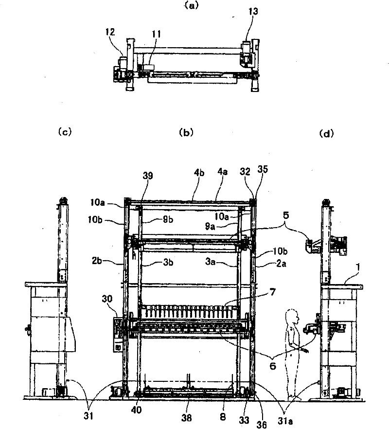
[0047] Next, use Figure 1 to Figure 12 Embodiments of the present invention will be described.

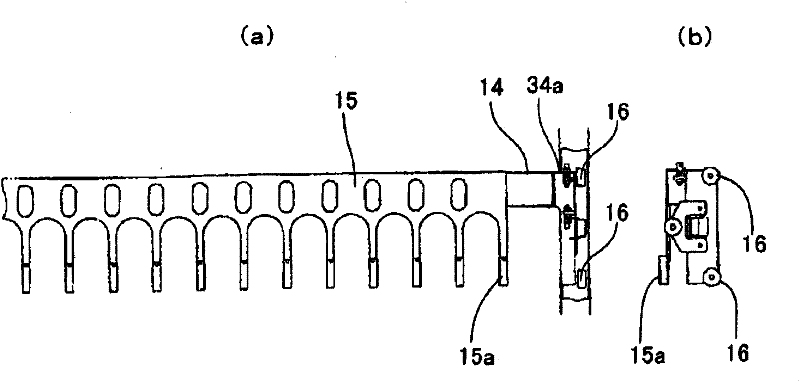
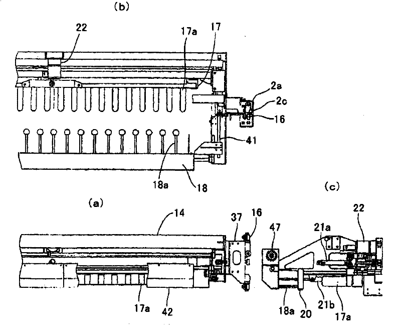
[0048] figure 1 It is an overall view of the curtain finishing device of the present invention, figure 2 (a) is an enlarged front view of the hook portion, (b) is a side view, image 3 (a) is a front view of the iron part, (b) is a top view, (c) is a side view, Figure 4 (a) is a plan view of the hem holding part (forming part) with the outside folding unit closed, (b) is a front view, (c) is a plan view of the hem holding part with the outside folding unit open, and (d) shows Side view of the closed state of the outer fold-in unit, (e) is a side view showing the open state of the aforementioned unit, Figure 5 (A) is a plan view of the hem holding part showing the shape of the inner and outer tuck-in tool suitable for finishing a curtain with a V-shaped sectional shape of the pleats, and (B) is a schematic sectional view of a normal tuck-in tool, (C) is a schematic cross-se...


PUM


Abstract

Disclosed is curtain finisher that enables heat treatment without shrinkage; easily forms uniform zigzag shapes (pleats) without requiring worker correction, and makes work efficient without applying unnecessary force on curtain fabric when forming zigzag shapes, and easily finishes curtain fabric in line with various curtain specifications (pleat pitches, pleat depths, pleat shapes, accessories, and the like). The curtain finisher is equipped with a hook portion that holds a curtain top; an iron portion containing a heater that rises and lowers between the curtain top and a hem portion while forming curtain pleats; a hem-holding portion composed of a backside-folding portion equipped at equidistant spacing with a folding tool in parallel, and a front-side folding portion disposed at half-pitches to mesh with the backside-folding portion, that rises and lowers between the curtain top and the hem portion; and an edge fastening portion for fastening a curtain edge. The backside-folding portion of the hem portion has a cylinder that houses at a leading edge a heater, and a bottom edge of the cylinder projects downward from the hem-holding portion bottom, excluding the cylinder portion, and the curtain hem when the hem-holding portion is lowered to the curtain hem portion.

Description

technical field [0001] The present invention relates to a curtain finishing device for finishing a plurality of corrugated plate-shaped pleats along the longitudinal direction of a sewn curtain in a suspended state. Background technique [0002] In the past, as a finishing device for finishing a curtain into a corrugated plate shape by heat treatment, there was provided a method in which corrugated pleats are formed on the lower part other than the top in the state where the sewn curtain is hung. A finishing device for curtains that performs finishing in the final process of production (Patent Document 1). [0003] More specifically, the curtain finishing device is characterized in that a curtain made of braided fabric containing thermoplastic synthetic fibers is hung with one or more pleats at predetermined intervals on the top, and it will be more durable than the curtain. The lower portion of the above-mentioned pleats is bent into a zigzag cross-section, and at least on...

Claims


Application Information

Patent Timeline
Patent Type & Authority Applications(China)
IPC IPC(8): A47H13/14
CPCD06J1/00
Inventor 井口雅敏
Owner KYOKUTO SANKI CO LTD
Why Eureka
Try Eureka