Method for operating an internal combustion engine

An internal combustion engine, crankcase technology, applied in mechanical equipment, engine components, machines/engines, etc.

Inactive Publication Date: 2011-11-16
AUDI AG
View PDF5 Cites 4 Cited by
  • Summary
  • Abstract
  • Description
  • Claims
  • Application Information

AI Technical Summary

Problems solved by technology

However, this entails significantly increased precision requirements, significant additional costs and increased friction performance of tight piston rings and pistons

Method used


Image

  • Method for operating an internal combustion engine
  • Method for operating an internal combustion engine
  • Method for operating an internal combustion engine

Examples


Embodiment Construction

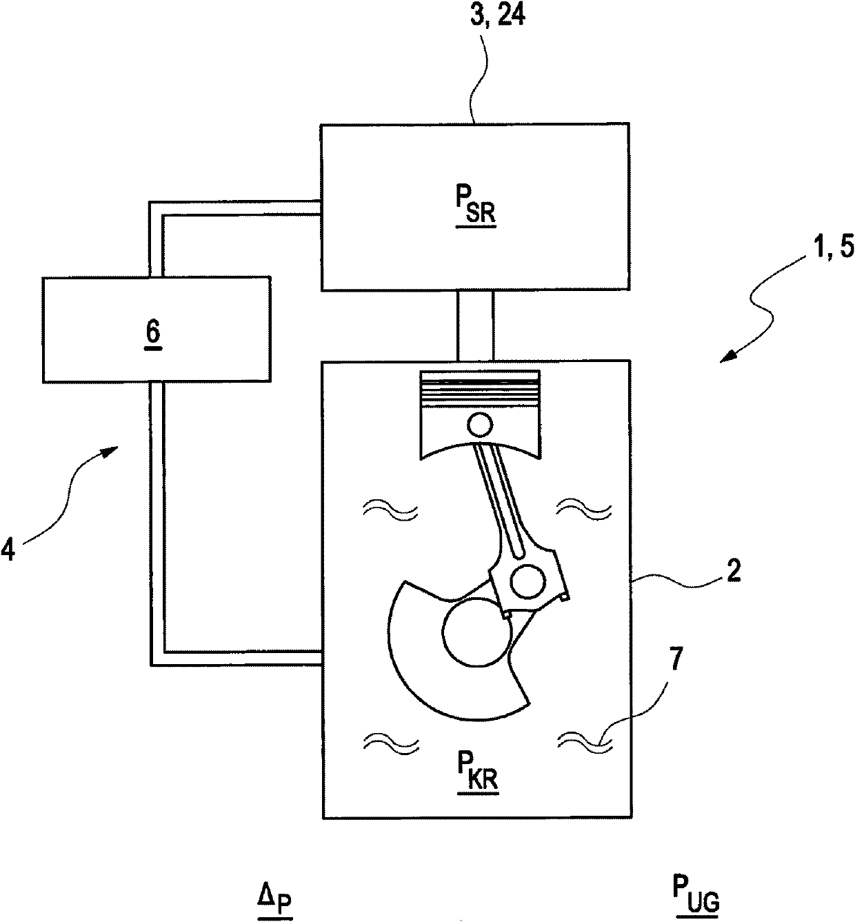
[0014] figure 1 An internal combustion engine 1 is shown schematically with a crankcase 2 and an intake manifold 3 forming an intake system 24 via which the internal combustion engine 1 is supplied with combustion air. The crankcase 2 and the intake manifold 3 are connected to one another via a crankcase ventilation device 4 . In the example shown, the internal combustion engine 1 is designed as a wet-sump naturally aspirated engine 5 . The crankcase ventilation device 4 has a pressure regulating valve 6 which makes it possible to adjust the negative pressure P present in the crankcase 2 in the following way KR Adjustment: The intake manifold negative pressure P present in the intake manifold 3 is adjusted by means of the pressure regulating valve 6 SR The crankcase 2 is loaded and the lubricant vapor 7 present in the crankcase is evacuated. The pressure regulating valve 6 is adapted here in such a way that the crankcase negative pressure P KR Relative to ambient pressure ...


PUM


Abstract

The invention relates to a method for operating an internal combustion engine having a crankcase, a crankcase vent, and a vacuum system. According to the invention, the pressure in the crankcase can be reduced as a function of a differential pressure between the vacuum system and the crankcase to a maximum of -500 mbar, particularly a maximum of -300 mbar, relative to the ambient pressure, for reducing lubricant consumption of the internal combustion engine.

Description

technical field [0001] The invention relates to a method for operating an internal combustion engine with a crankcase, a crankcase ventilation system and an air intake system. Background technique [0002] Vehicles with modern internal combustion engines have a crankcase ventilation which prevents lubricant, preferably oil or lubricant vapors, from being released into the environment. In the simplest case, the crankcase ventilation consists only of a pipe or hose connection between the crankcase of the internal combustion engine and the intake tract, where the negative pressure prevailing in the intake tract is responsible for sucking out the lubricant vapors in the crankcase . Depending on the design of the internal combustion engine and the lubricant circuit, an intake system constructed in this way can also include pressure regulating valves, throttles or auxiliary branches, which are arranged, for example, upstream of the throttle valve of the internal combustion engine...

Claims


Application Information

Patent Timeline
Patent Type & Authority Applications(China)
IPC IPC(8): F01M13/02
CPCF01M13/023F01M2013/0005
Inventor U·英格尔芬格M·罗森贝克
Owner AUDI AG
Why Eureka
Try Eureka