Drum brake type parking brake device

A technology of drum brakes and parking brakes, applied in the direction of drum brakes, mechanically driven drum brakes, brake types, etc., to achieve the effect of simplifying the structure, promoting size and weight, and promoting light weight

Inactive Publication Date: 2011-11-16
AKEBONO BRAKE IND CO LTD
View PDF10 Cites 3 Cited by
  • Summary
  • Abstract
  • Description
  • Claims
  • Application Information

AI Technical Summary

Problems solved by technology

However, in this structure described in PTL 5, the booster mechanism is composed only of a gear-type speed reducer and a transmission screw mechanism, both of which suffer from a large frictional loss, and thus, in order to secure a good braking force, it is necessary to use a large motor as a drive source

Method used


Image

  • Drum brake type parking brake device
  • Drum brake type parking brake device
  • Drum brake type parking brake device

Examples


no. 1 example

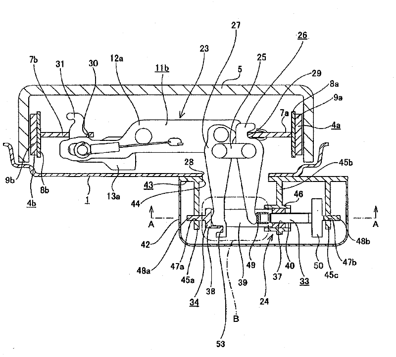
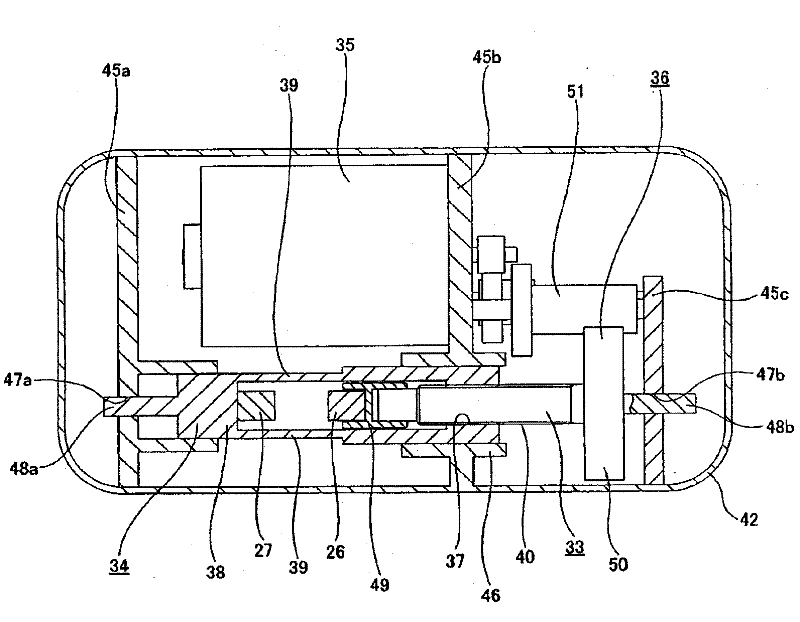
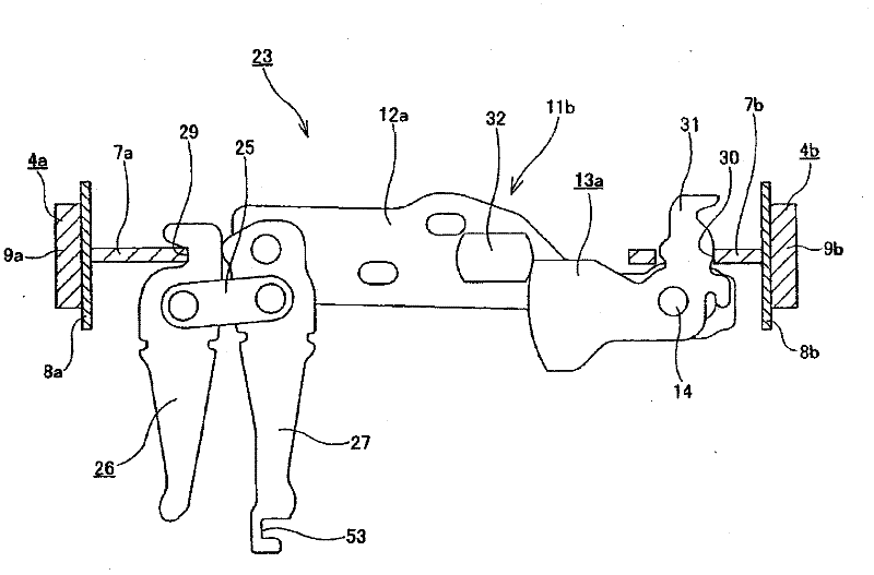
[0148] Figure 1 to Figure 5 The first example showing the embodiment of the present invention corresponds to the first to third, fifth and sixth inventions. In addition, the feature of the present invention including the present embodiment is the structure of the parking brake device used for the drum brake. In addition to the parking brake device, the structure and operation of the drum brake body are different from those mentioned above. Figure 15 to 20 The shown prior art structure is the same as the leader type drum brake widely known in the prior art, so illustrations and descriptions related to the same parts are omitted or simplified. Hereinafter, the characteristic part of the present invention will be mainly described.

[0149] An expansion and contraction device 23 for expanding and contracting the gap between the pair of brake shoes 4a and 4b is provided between the inner peripheral edges of the frame ribs 7a and 7b constituting the two brake shoes 4a and 4b, and Th...

no. 2 example

[0171] Image 6 9 shows a second example of the embodiment of the present invention, corresponding to the first, fourth and fifth inventions. In the case of this embodiment, the first and second pressing members that clamp and press the base end portions of the first and second expansion rods 26 and 27 from opposite sides are the cover 42a fixed to the back plate 1 and the support A threaded rod 54 is provided in the cover 42a so as to be swingable only in the axial direction. In addition, the threaded rod 54 is screwed into a threaded hole 56 provided in the middle portion of the reduction rotating member 55 rotatably supported in the cover 42a, such as a large reduction gear and a large reduction pulley. In addition, the speed reduction rotating member 55 is freely rotated and driven via the transmission belt 57 or the gear train by the motor constituting the driving source. In addition, the base end portions of the first and second expansion rods 26 and 27 are mutually supp...

no. 3 example

[0175] Picture 10 with Picture 11 The third example showing the embodiment of the present invention corresponds to the first to third, fifth and sixth inventions. In the case of this embodiment, compared with the case of the first embodiment of the foregoing embodiment, the female screw portion 37a is provided on the second pressing member 33a side, and the male screw portion 40a is provided on the first pressing member 34a side , And the two threaded portions 47a and 40a are screwed into each other. In addition, in order to clamp the base end portions of the first and second expansion rods 26a and 27a from opposite sides and enable the base end portions to be pressed by the two pressing members 33a and 34a, the two expansion rods 26a and The pressing target plate portions 64a and 64b are respectively provided in the side edge portions of the portion near the base end of 27a. The two pressing target plate portions 64a and 64b are directed by the metal plates constituting the...


PUM


Abstract

Achieved is a structure wherein there is adopted a link type force multiplication device that causes only a small transmission loss, wherein, as a result, miniaturization and weight saving can be brought about by using an electric motor with a relatively small output, and wherein, in addition, reaction force accompanying braking is offset in the aforementioned force multiplication device, with the result that no large force is applied to the connection between this force multiplication device and a back plate (1). A connection link (25), a strut (11c), and both first and second extension levers (26, 27) constitute an extension and retraction device (23). During braking, the base ends of both these levers (26, 27) are pressed in opposite directions to each other by both first and second pressing members (43, 33). Reaction force accompanying braking is offset in the connection link (25) section, with the result that no large force is applied to the back plate (1) or the like.

Description

Technical field [0001] The present invention relates to an improvement of a drum brake type parking brake device for maintaining a vehicle (automobile) in a parked state. Background technique [0002] In order to perform vehicle braking, drum brakes are widely used. Among drum brakes, various drum brakes are known, for example, as described in NPL 1. Among them, the leader-type drum brake is widely used because it obtains a stable braking force during forward and backward movement. Figure 15 to Figure 17 The leader type drum gear disclosed in PTL 1 is shown. The drum brake includes a back plate 1, an anchor 2, a wheel cylinder 3, a pair of brake shoes 4a and 4b, and a brake drum 5. [0003] Among them, the back plate 1 is supported and fixed to various constituent members of the suspension device such as the steering knuckle and the axle housing. In addition, the anchor 2 is supported and fixed to the portion near the outer side in the radial direction at one position in one cir...

Claims


Application Information

Patent Timeline
Patent Type & Authority Applications(China)
IPC IPC(8): F16D65/22F16D51/22F16D65/00
CPCF16D2121/14F16D2125/52F16D2121/24F16D2125/48F16D65/563F16D2123/00F16D2121/02F16D65/58F16D51/20F16D2125/565F16D2125/68F16D2125/64
Inventor 都竹春夫石川扩保池上洋柿崎英纪前原利史
Owner AKEBONO BRAKE IND CO LTD
Why Eureka
Try Eureka