Shaped anode and anode-shield connection for vacuum physical vapor deposition

A steam and physical technology, applied in the field of radio frequency sputtering physical vapor deposition, can solve problems such as film stability problems, and achieve the effect of stabilizing the deposition process

Active Publication Date: 2011-11-16
FUJIFILM CORP
View PDF4 Cites 3 Cited by
  • Summary
  • Abstract
  • Description
  • Claims
  • Application Information

AI Technical Summary

Problems solved by technology

Problems with process or film stability due to plasma spreading towards the chamber wall or deposition in reverse

Method used


Image

  • Shaped anode and anode-shield connection for vacuum physical vapor deposition
  • Shaped anode and anode-shield connection for vacuum physical vapor deposition
  • Shaped anode and anode-shield connection for vacuum physical vapor deposition

Examples


Embodiment Construction

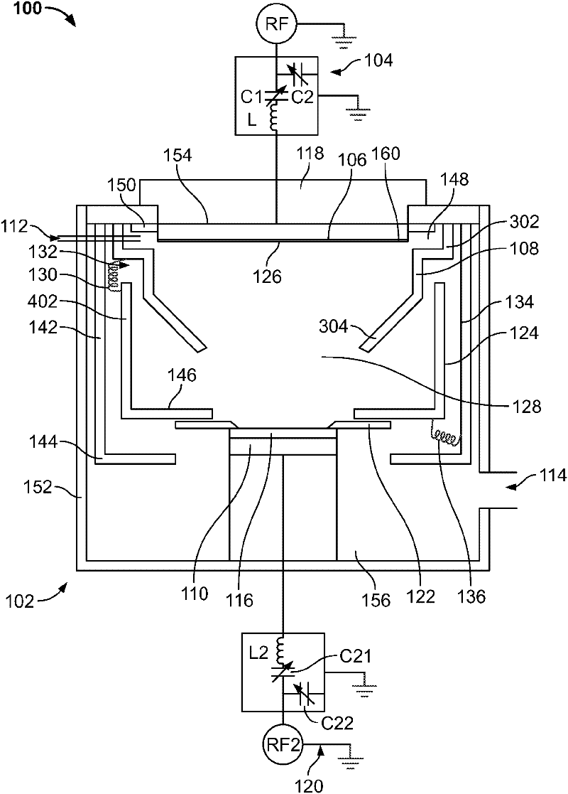
[0024] When RF physical vapor deposition or sputtering is used to form thin films on substrates, there can be variations in plasma density, or plasma can exist in undesired locations within the vacuum chamber, such as between the anode and shield, which can lead to Changes in deposited film properties. By varying the geometry, size and shape of the anode, shield, and electrical connections between the anode and shield, the properties of the deposited film can be controlled.

[0025] refer to figure 1 , the physical vapor deposition apparatus 100 may include a vacuum chamber 102 . The vacuum chamber 102 may be cylindrical and have side walls 152 , a top surface 154 and a bottom surface 156 . Magnetron assembly 118 may be located on top of vacuum chamber 102 . The magnetron assembly 118 may include a set of magnets having alternating poles. The magnetron assembly 118 may be stationary or may rotate about an axis perpendicular to the radius of the vacuum chamber 102 . The ph...


PUM


Abstract

A physical vapor deposition apparatus includes a vacuum chamber with side walls, a cathode, a radio frequency power supply, a substrate support, a shield, and an anode. The cathode is inside the vacuum chamber, and the cathode is configured to include a sputtering target. The radio frequency power supply is configured to apply power to the cathode. The substrate support is inside and electricallyisolated from the side walls of the vacuum chamber. The shield is inside and electrically connected to the side walls of the vacuum chamber. The anode is inside and electrically connected to the sidewalls of the vacuum chamber. The anode includes an annular body and an annular flange projecting inwardly from the annular body, and the annular flange is positioned to define a volume below the target for the generation of plasma.

Description

technical field [0001] The present disclosure relates generally to radio frequency (RF) sputtering physical vapor deposition (PVD), and more particularly to shaped anodes and ribbons for RF sputtering PVD devices. Background technique [0002] Radio frequency sputtering PVD is a method used to deposit thin films on substrates. The substrate is placed in the vacuum chamber facing the target connected to an RF power source. When RF power is applied, a plasma is formed. Positive gas ions are pulled toward the target surface, impact the target volume, and remove target atoms through momentum transfer. The removed target atoms are then deposited on the substrate to form a thin film layer. [0003] During physical vapor deposition, it is important to control the properties of the deposited film. Due to the plasma spreading towards the chamber wall or deposition against it, problems arise with regard to the stability of the process or the film. Contents of the invention [0...

Claims


Application Information

Patent Timeline
Patent Type & Authority Applications(China)
IPC IPC(8): H01L21/203
CPCC23C14/08H01J37/3447H01J37/3438C23C14/35H01J37/3408H01L21/203
Inventor 李有明杰弗里·比克迈尔
Owner FUJIFILM CORP
Why Eureka
Try Eureka