Eureka AIR delivers breakthrough ideas for toughest innovation challenges, trusted by R&D personnel around the world.

Air pressure pipe bending machine

A technology of pipe bending machine and air pressure, which is applied in the field of air pressure pipe bending machines, which can solve the problems of high labor intensity of manual pipe bending, damage to the insulation layer of wires in the pipe, and low quality of pipe bending, so as to achieve beautiful installation effect, reduce material loss, and bend good tube quality

Active Publication Date: 2011-11-23
GOLD MANTIS CONSTR DECORATION
View PDF4 Cites 13 Cited by
  • Summary
  • Abstract
  • Description
  • Claims
  • Application Information

AI Technical Summary

Problems solved by technology

[0002] At present, in the field of building electrical construction, the bending pipes of steel conduits are mainly bent by hand-pulled pipe benders. The quality of the bent pipes is not high, which is easy to cause bending and deflation, resulting in damage to the insulation layer of the wires in the pipe.
Manual pipe bending is labor intensive and construction efficiency is low
And the short pipes cut off on site can no longer be used, resulting in waste of steel pipes

Method used


Image

  • Air pressure pipe bending machine
  • Air pressure pipe bending machine

Examples


Embodiment

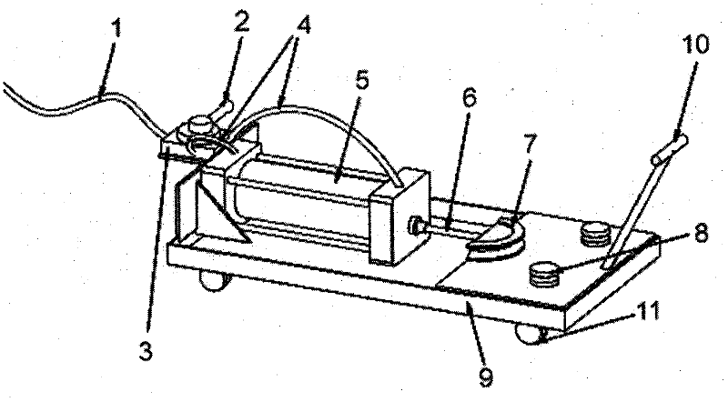
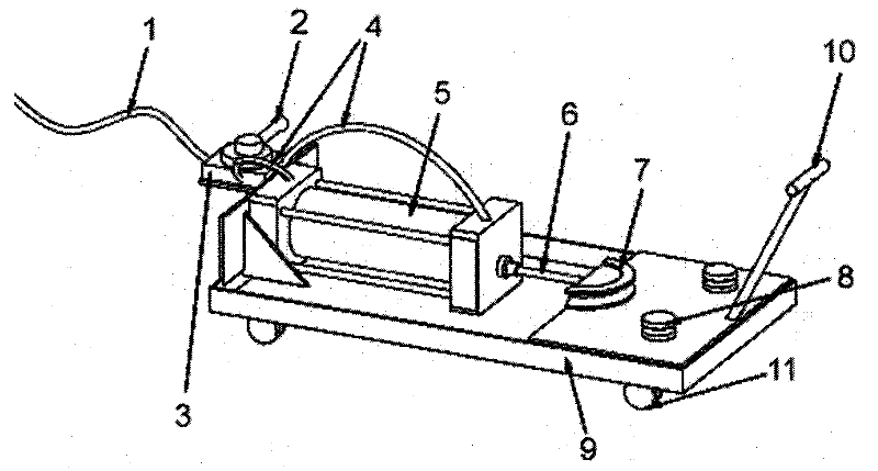
[0024] Example: such as figure 1 As shown, a pneumatic pipe bending machine includes an air intake pipe 1, a joystick 2, an air valve 3, a pneumatic hose 4, a cylinder 5, a telescopic shaft 6, a pipe bending groove 7, a rolling groove 8, a base 9, Drag pull bar 10, drag pulley 11.

[0025] One end of the intake pipe 1 is connected to the air pump, and the other end is connected to the air valve 3. The air valve 3 has two air outlets, and the two ends of the air cylinder 5 are connected by a pneumatic hose 4. When the air pressure hose 4 is connected with the air inlet of the cylinder 5, a sealing ring socket is used.

[0026] The air valve 3 is provided with a control handle 2 to control the air intake direction of the cylinder 5 . The output air pressure of the air pump is usually 8Kg when it is running. When the control handle 2 is turned to the direction of the workbench, the air pressure is loaded on the piston of the cylinder 5, and an air pressure difference is generat...


PUM


Abstract

The invention discloses an air pressure pipe bending machine. The machine comprises a worktable, a cylinder (5), a cylinder component, a pipe bending pressure tank (7) and rolling grooves (8), wherein a cylinder piston of the cylinder (5) is connected with the pipe bending pressure tank (7) through a telescopic shaft rod (6); the pipe bending pressure tank (7) is provided with a semi-circular notch of which the diameter is matched with that of a pipe; the worktable is provided with two rolling grooves (8) for positioning the two ends of the pipe and matching with the pipe bending pressure tank (7) to bend the pipe; each rolling groove (8) is provided with a semi-circular notch of which the diameter is matched with that of the pipe; and the cylinder piston moves forwards or backwards to push the telescopic shaft rod (6) and the pipe bending pressure tank (7) to move forwards or backwards along the direction of the worktable. The machine is high in pipe bending quality, ensures consistent and attractive bends, has high work efficiency, is not required to be operated by professional personnel, saves labor cost, is suitable for bending short pipes, can improve the utilization rate of the short pipes in a construction site, and reduces material loss.

Description

technical field [0001] The invention relates to a pneumatic pipe bending machine. Background technique [0002] At present, in the field of building electrical construction, the bending pipes of steel conduits are mainly bent by hand pipe benders. The quality of the pipe bends is not high, and it is easy to cause bending and collapse, resulting in damage to the insulation layer of the wires in the pipe. Manual pipe bending is labor intensive and construction efficiency is low. And the short pipes cut off on site can no longer be used, resulting in waste of steel conduits. Contents of the invention [0003] The object of the present invention is to provide a pneumatic pipe bending machine with simple structure, good pipe bending quality and high working efficiency. [0004] The technical solution of the present invention is: a pneumatic pipe bending machine, which includes a workbench, a cylinder and a cylinder assembly, a pipe bending groove, and a rolling groove. The p...

Claims


Application Information

Patent Timeline
Patent Type & Authority Applications(China)
IPC IPC(8): B21D7/06
Inventor 刘国良杨震李斌季军蒋晓芳王志祥陈伟林展进宏钱新元汪建垚张治平夏策峰唐江李晓宇孔建林周荣
Owner GOLD MANTIS CONSTR DECORATION
Why Eureka
Eureka Blog
Learn More