

Brake system of motor vehicle
A brake system and motor vehicle technology, applied in the direction of brakes, brake components, vehicle parts, etc., can solve the problems of locked wheels, complex structure, high cost, etc., to reduce side slip, avoid side slip, and good adaptability Effect
- Summary
- Abstract
- Description
- Claims
- Application Information
AI Technical Summary
Problems solved by technology
Method used
Image

Examples
Embodiment Construction
[0029] The present invention will be further described below with reference to the accompanying drawings.
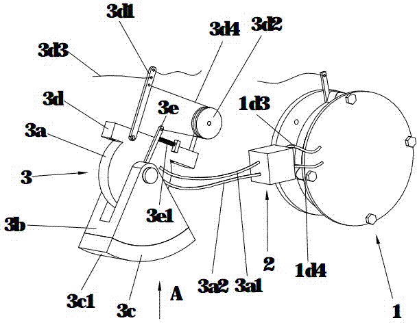
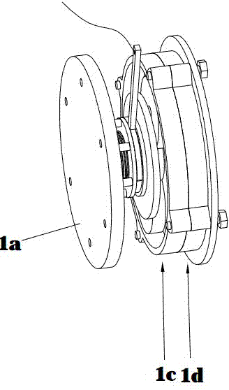
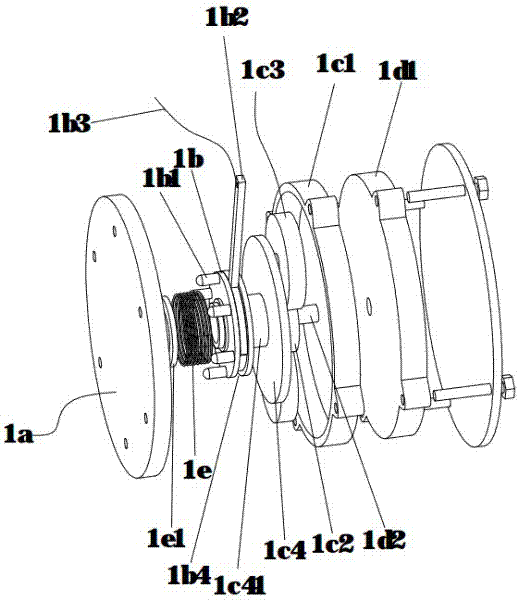
[0030] Such as Figures 1 to 6 As shown, the present invention mainly includes three parts, namely the power conversion component 1 , the hydraulic control component 2 and the brake component 3 . The power conversion component 1 includes a flange 1a connected to the hub of the vehicle, and the flange 1a is used to transmit the rotation speed of the wheel to the oil pump 1d fixedly installed on the vehicle frame. A speed-up mechanism 1c is provided between the flange 1a and the oil pump 1d. The speed-up mechanism 1c is a planetary gear train speed-up mechanism, including a ring gear 1c1. The ring gear 1c1 and the oil pump housing 1d1 are fixedly connected by bolts and fixed together on the frame. The sun gear 1c2 in the speed-up mechanism 1c is coaxial with the oil pump spindle 1d2, the sun gear 1c2 meshes with the planetary gear 1c3, and the planetary gear 1c3 meshes w...
PUM
 Abstract
Description
Claims
Application Information