Manufacturing system for vacuum glass

A technology of vacuum glass and manufacturing system, applied in the field of vacuum glass, can solve problems such as affecting the quality of vacuum glass, insufficient vacuum degree, complicated setting, etc., and achieve the effects of high connection efficiency, improved production efficiency, and improved quality

Active Publication Date: 2011-11-23
TIANJIN GUSHANG VACUUM GLASS MFG
View PDF8 Cites 2 Cited by
  • Summary
  • Abstract
  • Description
  • Claims
  • Application Information

AI Technical Summary

Problems solved by technology

The shortcoming that above-mentioned two kinds of methods exist is: 1, in the existing vacuum heating furnace, glass supports are placed parallelly up and down, the spacing between each layer of glass supports is 15-25cm, and each layer of glass supports is equipped with a cooling water device The suction head is connected to the suction pipe installed in the vacuum glass. The vacuum unit is installed outside the furnace, and the vacuum is sealed in the furnace, thus completing the manufacture of vacuum glass. However, this structure makes the unit volume in the furnace set Complicated, few layers, low output; 2. The existing vacuum glass suction head device has a complex structure, difficult connection, easy to break, and water cooling is prone to water leakage and cause accidents; 3. The existing vacuum glass suction pipe It is a through hole. During the cooling process of the vacuum glass after edge sealing, there is still some moisture in the vacuum chamber. Although the moisture can be absorbed by the getter, there is also the problem of insufficient vacuum degree that affects the vacuum. The quality of glass; 4. The existing heating furnace and vacuum furnace have their own functions, basically there is no organic connection, and the energy consumption is relatively large

Method used


Image

  • Manufacturing system for vacuum glass
  • Manufacturing system for vacuum glass
  • Manufacturing system for vacuum glass

Examples


Embodiment Construction

[0019] The present invention will be further described in detail below in conjunction with the accompanying drawings and through specific embodiments. The following embodiments are only descriptive, not restrictive, and cannot limit the protection scope of the present invention.

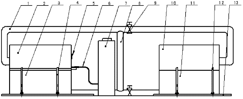
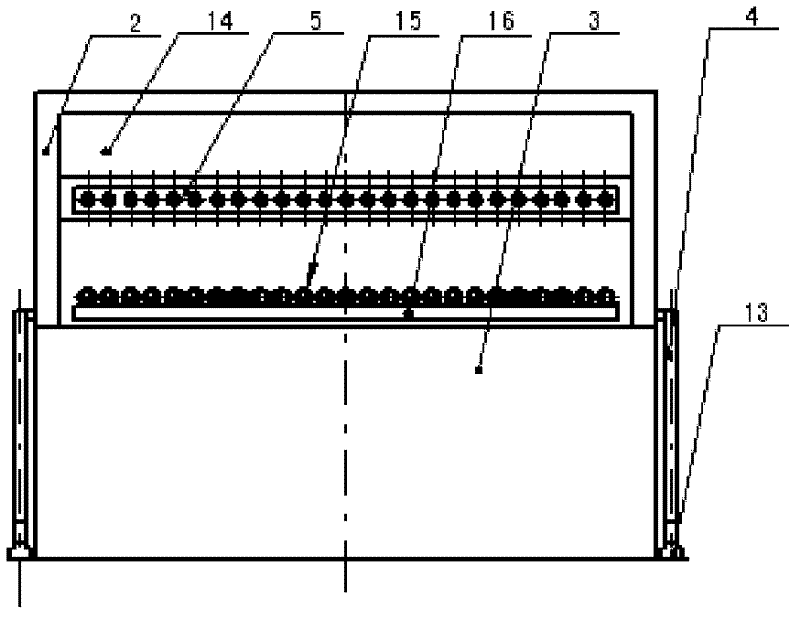
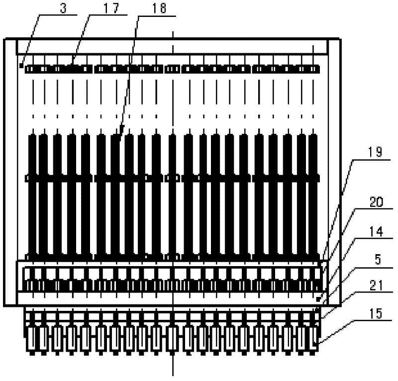
[0020] A kind of manufacturing system of vacuum glass, see figure 1 , 2 , 3, including a high-temperature heating box and a low-temperature sealing box. The high-temperature heating box is composed of a movable sealing box cover 10 and a heating box 11. The moving sealing box cover is a door-type structure, and the sealing cover is installed on the heating box. The moving sealing box cover and the heating box are all equipped with thermal insulation materials, and mobile brackets 12 are installed on both sides of the mobile sealing box cover. Slide left and right to open or close the heating box.

[0021] The low-temperature sealing box is composed of a mobile sealing box cover 2 and an air extract...


PUM


Abstract

The invention relates to a manufacturing system for vacuum glass. The system comprises a high-temperature heating box, a low-temperature sealing box and a vacuum pump, wherein a communicated hot air pipe is arranged between the high-temperature heating box and the low-temperature sealing box; the low-temperature sealing box consists of a movable sealing box cover and a pumping box; and the movable sealing box cover and the pumping box are arranged hermetically. The manufacturing system for vacuum glass consists of the high-temperature heating box and the low-temperature sealing box, and a hot air pipeline of the low-temperature sealing box is communicated with a pipeline of the high-temperature heating box, therefore the waste heat of the high-temperature heating box can be fully utilized by a low-temperature vacuum furnace so as to remove moisture from a vacuum glass vacuum cavity. The manufacturing system for vacuum glass has the advantages of environment friendliness, energy conservation and capabilities of removing the moisture from the vacuum glass and improving the quality of vacuum glass; moreover, the entire manufacturing system is combined organically, so that continuous production of vacuum glass is facilitated, and the production efficiency is increased.

Description

technical field [0001] The invention belongs to the field of vacuum glass, in particular to a vacuum glass manufacturing system. Background technique [0002] At present, the traditional vacuum glass manufacturing method is to lay supports on the substrate glass, and then combine the sheets, seal the edges, make air extraction holes, install air extraction pipes, and place the two pieces of glass flat in the heating furnace for heating and edge sealing. Then take it out for vacuuming, and after fusing the exhaust pipe, vacuum glass can be formed. Alternatively, heating and edge sealing and vacuuming can also be carried out directly in a vacuum heating furnace. The shortcoming that above-mentioned two kinds of methods exist is: 1, in the existing vacuum heating furnace, glass supports are placed parallelly up and down, the spacing between each layer of glass supports is 15-25cm, and each layer of glass supports is equipped with a cooling water device The suction head is con...

Claims


Application Information

Patent Timeline
Patent Type & Authority Applications(China)
IPC IPC(8): C03C27/06
Inventor 左树森
Owner TIANJIN GUSHANG VACUUM GLASS MFG
Why Eureka
Try Eureka