Cylinder head drain and vent

A cylinder head, channel technology, applied in the field of drainage and ventilation, can solve the problems of insufficient oil cooling, restricting ventilation and oil drainage, increasing the possibility of oil coking, etc.

Active Publication Date: 2011-11-23
GM GLOBAL TECH OPERATIONS LLC
View PDF8 Cites 15 Cited by
  • Summary
  • Abstract
  • Description
  • Claims
  • Application Information

AI Technical Summary

Problems solved by technology

Due to the cylinder head construction required by the central DI it was very difficult to connect the intake and exhaust chambers to allow drainage and ventilation between these chambers
The cylinder head cover may provide an opening in the central recess such that the central recess is uncovered to provide access to the injectors and spark plugs, which may restrict ventilation and leakage between the intake and exhaust chambers and through the cylind...

Method used


Image

  • Cylinder head drain and vent
  • Cylinder head drain and vent
  • Cylinder head drain and vent

Examples


Embodiment Construction

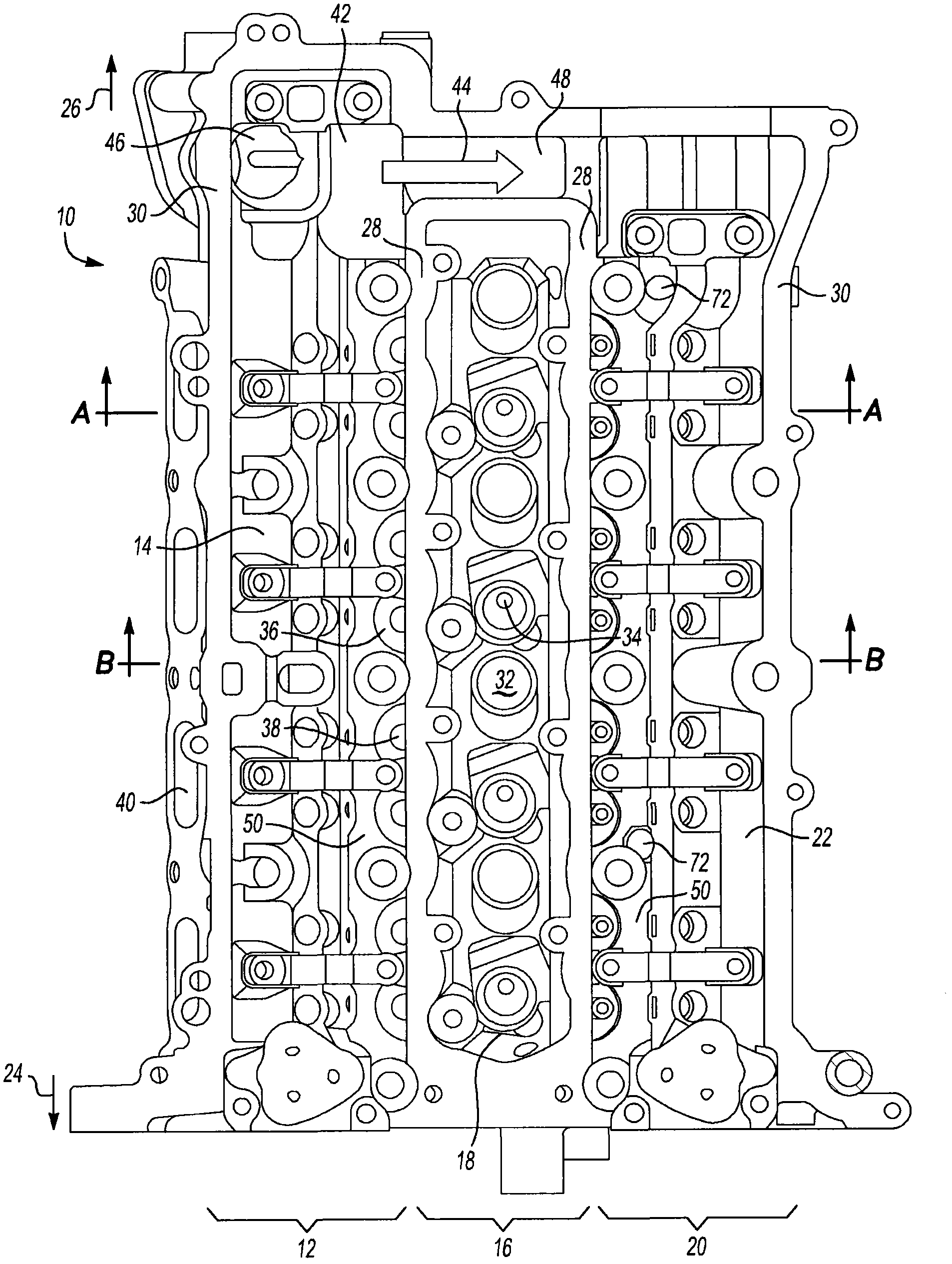
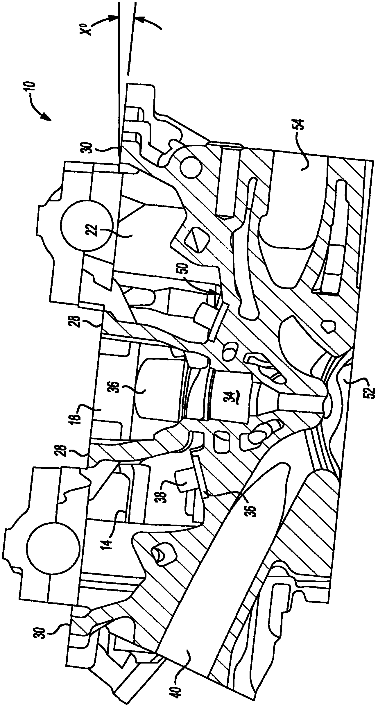
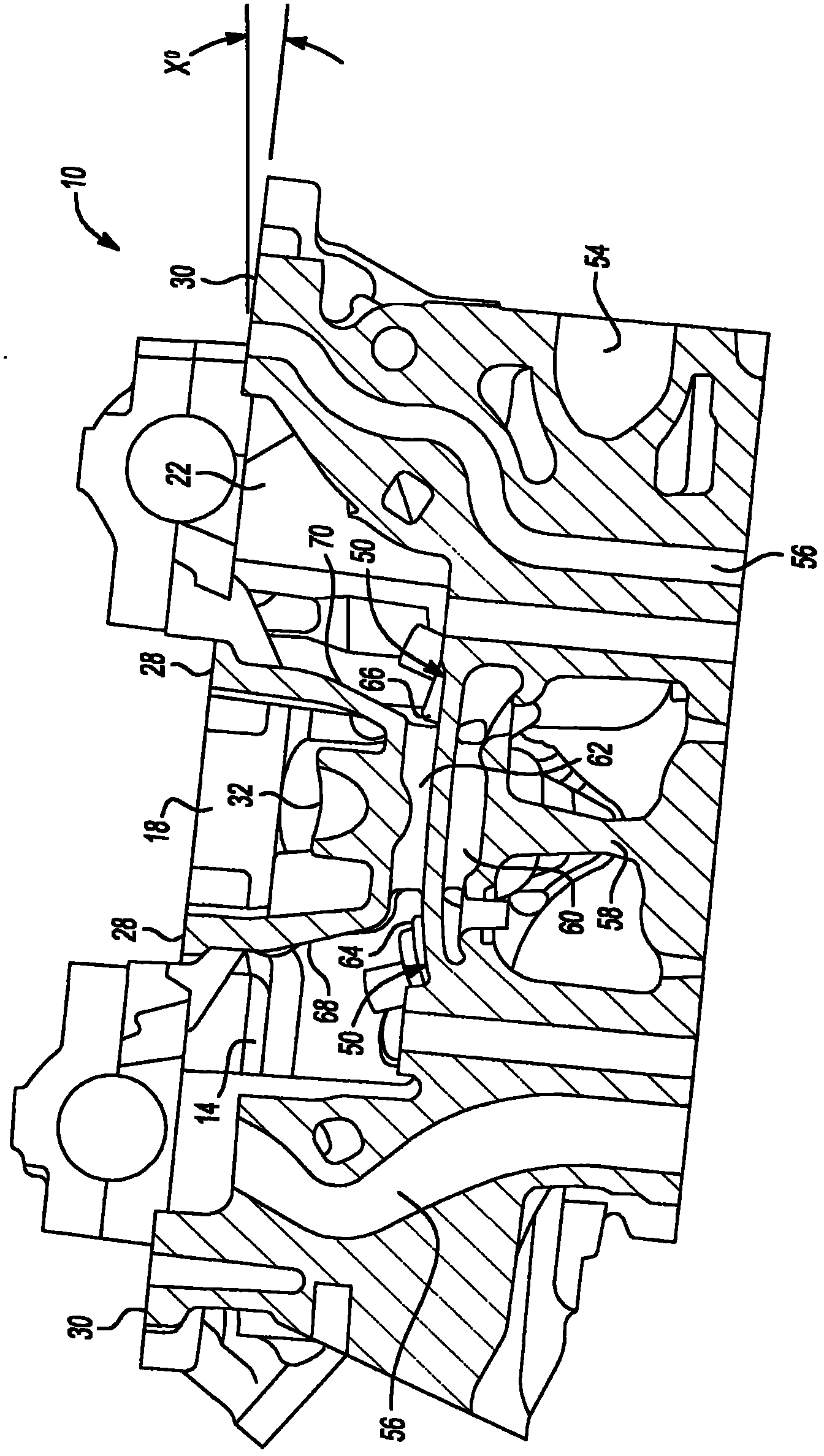
[0056] Referring to the drawings, wherein like reference numerals designate like parts throughout the several views, and from figure 1Initially, a schematic top view of a partially assembled cylinder head is indicated generally at 10 . Cylinder head 10 is typically formed as a casting of aluminum or cast iron and may be otherwise finished by machining, grinding, or other processes. Cylinder head 10 (which may also be referred to as head 10 ) is configured to include a first side 12 and a second side 20 extending from a front portion of head 10 generally along a longitudinal axis of head 10 . 24 to a rear portion 26 and are separated by a central portion 16 . The first chamber 14 is defined by the first side 12 of the cover 10 and the second chamber 22 is defined by the second side 20 of the cover 10 .

[0057] Central portion 16 defines a valley 18 extending generally along the longitudinal axis of the cylinder head and generally separating chamber 14 from chamber 22 . Disp...


PUM


Abstract

A central direct injection (DI) cylinder head is configured with an intake valvetrain and an exhaust valvetrain separated by an uncovered central DI valley. The uncovered central DI valley limits oil flow from the high side chamber to the low side chamber and PCV transfer. Oil drainage and additional PCV transfer between the intake and exhaust chambers is provided by drain/vent passages integrally cast into the casting of the cylinder head. The drain/vent passages may be of varying configuration, and may be located between an injector port of a first cylinder set and a spark plug port of an adjacent cylinder set, or at either or both ends of the cylinder head. A method is provided to form a casting of the cylinder head as described herein, including casting of a plurality of drain/vent passages between the first chamber and the second chamber of the cylinder head.

Description

[0001] Cross References to Related Applications [0002] This application claims the benefit of US Provisional Patent Application No. 61 / 345,384, filed May 17, 2010, which is hereby incorporated by reference in its entirety. technical field [0003] The invention relates to drainage and ventilation of cylinder heads. Background technique [0004] Central direct injection (DI) engine cylinder heads are typically configured with intake and exhaust valvetrains separated by a central recess that includes the injector and spark plug. Due to the cylinder head configuration required by the central DI, it is very difficult to connect the intake and exhaust chambers to allow drainage and ventilation between these chambers. The cylinder head cover may provide an opening in the central recess such that the central recess is uncovered to provide access to the injectors and spark plugs, which may restrict ventilation and leakage between the intake and exhaust chambers and through the cy...

Claims


Application Information

Patent Timeline
IPC IPC(8): F02F1/42F01M9/10
CPCF01M9/10F01M13/00B22C9/103Y10T29/4927
Inventor R·E·巴克R·M·比特纳B·W·盖泽P·A·辛诺特
Owner GM GLOBAL TECH OPERATIONS LLC
Why Eureka
Try Eureka