

Synchronizer assembly
A synchronizer and assembly technology, applied to clutches, mechanically driven clutches, mechanical equipment, etc., can solve the problems of synchronizer failure, large moment of inertia, and large impact of lock pins, etc., and achieve long service life, firm structure, and simple effect
Inactive Publication Date: 2011-11-23
万沛
View PDF3 Cites 1 Cited by
- Summary
- Abstract
- Description
- Claims
- Application Information
AI Technical Summary
Problems solved by technology
[0002] At present, most of the lock-pin synchronizer assemblies used in automobiles are of traditional structure. Its disadvantages are that the weight of the gear sleeve is heavy, the moment of inertia is large, and the synchronization performance is not ideal. The impact is so loud that the locking pin breaks easily, rendering the synchronizer useless
Method used
View moreImage
Smart ImageViewing Examples

Examples
Embodiment Construction
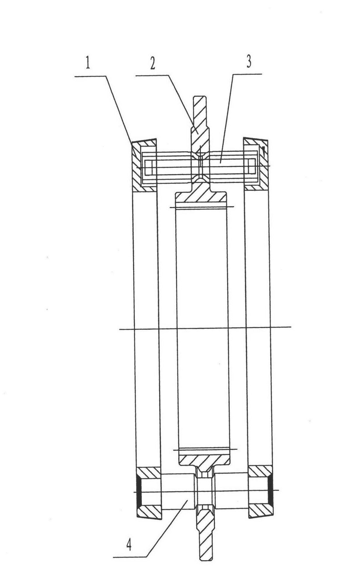
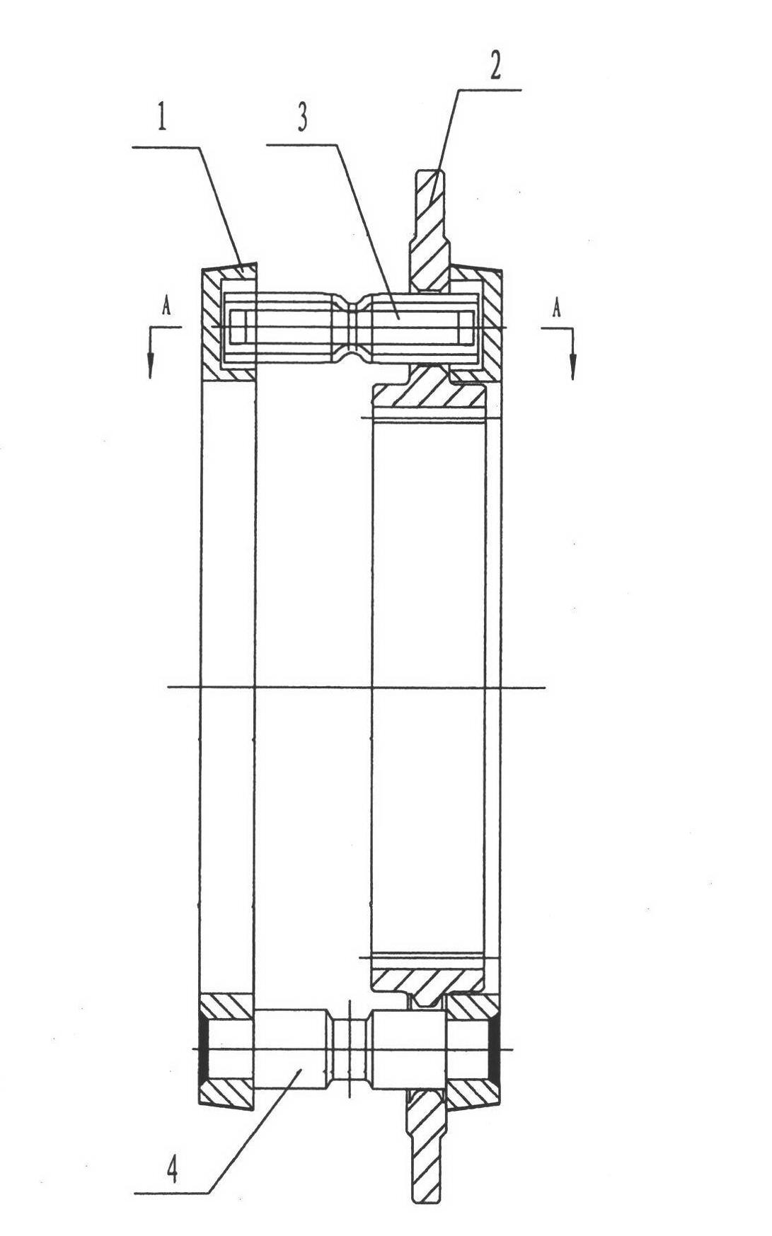
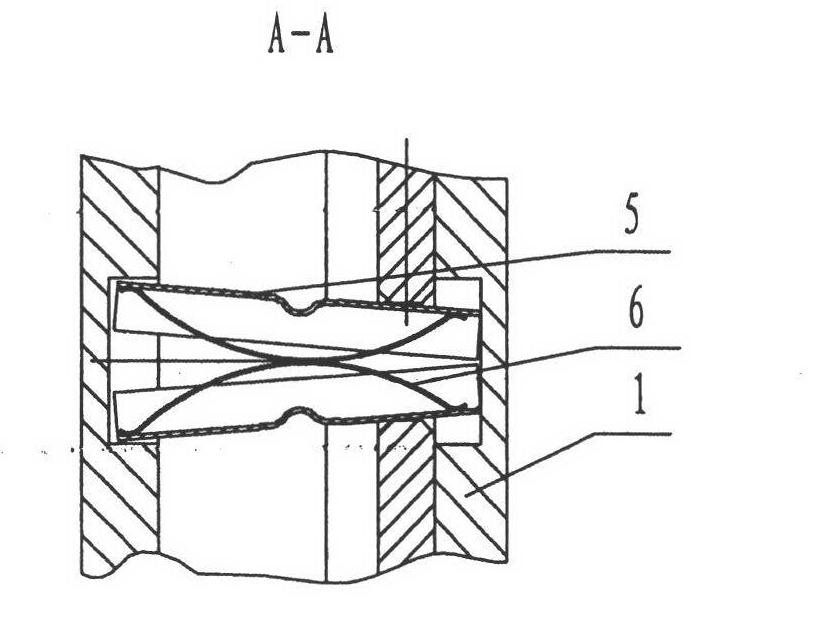
[0010] Such as figure 1 , figure 2 and image 3 As shown, the present invention is a synchronizer assembly, which includes two synchronous rings 1, a sliding tooth sleeve 2, three sets of positioning pin systems 3 and three lock pins 4, and the surface of the synchronous ring 1 is bonded with wear-resistant carbon fiber Cloth; the structure of the sliding gear sleeve 2 is different from the traditional one. There is no fork slot on the edge of the sliding gear sleeve 2, which is a fork plate structure; the positioning pin system 3 consists of two semicircular positioning pins 5 and two bow springs 6 form.
Login to View More PUM
 Abstract
The invention discloses a synchronizer assembly which comprises two synchronous rings (1), a sliding toothed sleeve (2), three locating pin systems (3) and three lockpins (4), wherein the sliding toothed sleeve (2) is in a shift fork plate type structure; and each locating pin systems comprises two semicircular locating pins (5) and two bow springs (6). The synchronizer assembly disclosed by the invention has the advantages of gear release prevention, high synchronization speed, light weight, material conservation, energy conservation, long service life, short gear shift synchronization time and the like.
Description
technical field [0001] The invention relates to a synchronizer assembly. Background technique [0002] At present, most of the lock-pin synchronizer assemblies used in automobiles are of traditional structure. Its disadvantages are that the weight of the gear sleeve is heavy, the moment of inertia is large, and the synchronization performance is not ideal. The impact is so loud that the locking pin breaks easily, rendering the synchronizer useless. Contents of the invention [0003] Aiming at the deficiencies of the prior art, the present invention provides a light-duty, out-of-gear-proof synchronizer assembly, which has the advantages of preventing out-of-gear, fast synchronization, light weight, material saving, energy saving, and long service life. [0004] The present invention adopts the following scheme: a synchronizer assembly, which is composed of two synchronizing rings, a sliding gear sleeve, three sets of positioning pin systems and three locking pins, the slid...
Claims
Login to View More Application Information
Patent Timeline
 Patent Type & AuthorityApplications(China)
IPC IPC(8): F16D23/04
Inventor万沛米卫强
Owner万沛