
Dust particle detection device

A particle detection device, dust technology, applied in the direction of measuring devices, particle size analysis, individual particle analysis, etc., can solve the problems that affect the accuracy of detection results, laser stray light treatment is not thorough, and achieve the effect of improving accuracy

Pending Publication Date: 2021-12-21
麦克微尔(天津)科技有限公司
View PDF0 Cites 0 Cited by
  • Summary
  • Abstract
  • Description
  • Claims
  • Application Information

AI Technical Summary

Problems solved by technology

[0005] The invention provides a dust particle detection device to solve the problem that the existing detection device does not process laser stray light thoroughly and affects the accuracy of detection results

Method used


Image

  • Dust particle detection device
  • Dust particle detection device
  • Dust particle detection device

Examples


Embodiment Construction

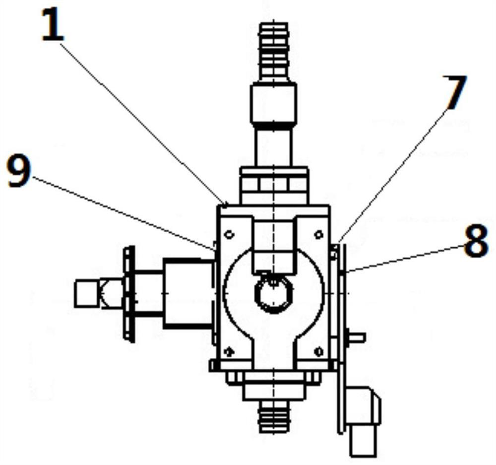
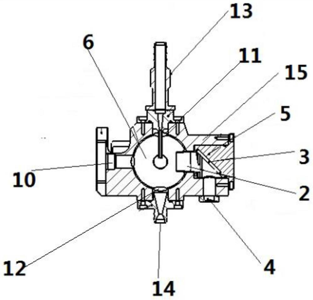
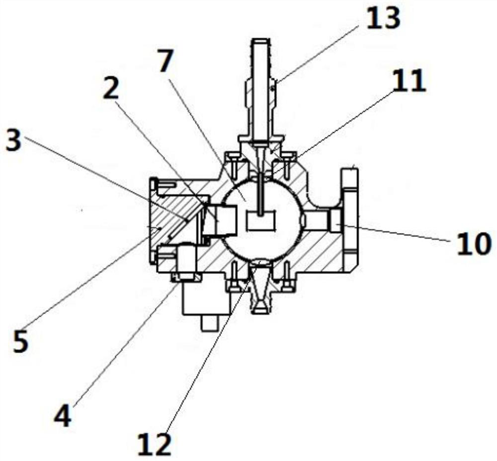
[0039] The specific implementation manners of the present invention will be further described in detail below in conjunction with the accompanying drawings and embodiments. The following examples are used to illustrate the present invention, but are not intended to limit the scope of the present invention.

[0040] In the description of this application, it is to be understood that the terms "center", "upper", "lower", "front", "rear", "left", "right", "vertical", "horizontal", The orientations or positional relationships indicated by "top", "bottom", "inner", "outer", etc. are based on the orientations or positional relationships shown in the drawings, and are only for the convenience of describing the application and simplifying the description, rather than indicating or implying References to devices or elements must have a particular orientation, be constructed, and operate in a particular orientation and therefore should not be construed as limiting the application.

[0...


PUM


Abstract

The invention relates to the technical field of dust particle detection, and discloses a dust particle detection device. The device comprises a shell in which a measurement cavity is formed, and the shell is provided with an exit port communicating with the measurement cavity; an attenuation part is connected with the shell; the attenuation part comprises an attenuation cylinder which is communicated with the measurement cavity and is used for limiting the laser stray light entering the attenuation cylinder from being reflected back into the measurement cavity, an attenuation piece which is used for absorbing and reflecting laser stray light entering the attenuation part from the measurement cavity, and a dissipation cover which is arranged on the shell and is used for absorbing the laser stray light reflected by the attenuation piece. According to the dust particle detection device, the attenuation part can absorb a large amount of laser stray light, so that the laser stray light is effectively prevented from returning to the measurement cavity, and the accuracy of a detection result is improved.

Description

technical field [0001] The invention relates to the technical field of dust particle detection, in particular to a dust particle detection device. Background technique [0002] Particles in the air will scatter under the irradiation of light. This phenomenon is called light scattering. Light scattering is related to factors such as particle size, light wavelength, particle refractive index and particle absorption characteristics of light. The specific working principle of the dust particle counter: the light from the light source is focused in the measurement cavity by the lens group, and when each particle in the air passes through the measurement cavity quickly, the incident light is scattered once to form an optical pulse signal. This optical signal is sent to the photodetector through the lens group 2, and converted into an electrical pulse signal proportionally, and then amplified and screened by the electronic circuit of the instrument to pick out the required signal a...

Claims


Application Information

Patent Timeline
IPC IPC(8): G01N15/06G01N15/02G01N15/10
CPCG01N15/06G01N15/0205G01N15/10G01N15/075
Inventor 潘杰茹敬会闫庆鹏范海悦赵斌
Owner 麦克微尔(天津)科技有限公司
Learn More