Method for compensating and regulating heating temperature of centralized heat supply network

An adjustment method and temperature compensation technology, applied in space heating and ventilation details, household heating, heating methods, etc., can solve the problems of reducing emissions and saving fuel, and achieve the goals of reducing emissions, saving fuel, and being easy to operate and realize Effect

Inactive Publication Date: 2011-11-23
江丛兴
View PDF4 Cites 18 Cited by
  • Summary
  • Abstract
  • Description
  • Claims
  • Application Information

AI Technical Summary

Problems solved by technology

[0003] In order to solve the problem that the existing heating boiler temperature control method cannot save fuel, reduce emissions, and make the indoor temperature of the user reach the standard, the invention further provides a heating temperature compensation and adjustment method for the central heating network

Method used


Image

  • Method for compensating and regulating heating temperature of centralized heat supply network
  • Method for compensating and regulating heating temperature of centralized heat supply network

Examples


specific Embodiment approach 1

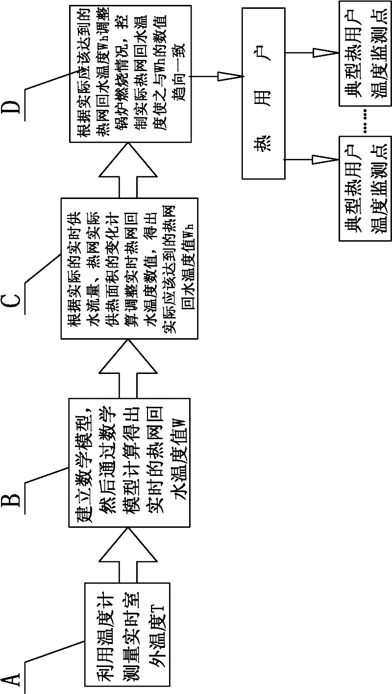
[0033] Specific implementation mode one: as figure 1 As shown, the specific process of a heating temperature compensation adjustment method for a central heating network described in this embodiment is:

[0034] Step A, using a thermometer to measure the real-time outdoor temperature T;

[0035] Step B, establish a mathematical model, and then calculate the real-time return water temperature value W of the heating network through the mathematical model. The specific process is:

[0036] Step B1, when the outdoor temperature T is 0°C, W=38.5°C;

[0037] Step B2, when the outdoor temperature T>0°C, W=38.5-0.65×|W1|;

[0038] Step B3, when the outdoor temperature T<0°C and ≥-20°C, W=38.5+K1×|W1|;

[0039] Step B4. When the outdoor temperature T<-20°C,

[0040] W=38.5+K1×20+K2×(|W1|-20);

[0041] In the formula:

[0042] W represents the return water temperature value of the heating network calculated according to the outdoor air temperature, in °C;

[0043] |W1| indicates ...

specific Embodiment approach 2

[0054] Specific implementation mode two: In this implementation mode, in step D, control the return water temperature W of the heating network h1 and the actual return water temperature of the heating network that should be achieved W h The absolute value of the difference between the two is less than or equal to 0.5°C. Other steps are the same as in the first embodiment.

[0055] The hardware needed to realize the method of the present invention includes a thermometer, a temperature signal transmitter, an outdoor shutter box, a transmission cable, a DCS system for controlling boiler combustion, and the like. According to the difference of the computer languages ​​used in the DCS system for controlling boiler combustion, the method of the present invention is programmed and written into the computer of the DCS system. Measure the outdoor temperature T through a thermometer, and then convert the temperature signal into an electrical signal through a temperature signal transmi...


PUM


Abstract

The invention relates to a method for compensating and regulating the heating temperature of a centralized heat supply network, and belongs to the technical field of heat supply regulation. By the method, the problem that the aims of saving fuel, reducing discharge and allowing the indoor temperature of users to reach the standard cannot be fulfilled by the conventional method for controlling the temperature of a heating boiler. The method comprises the following steps of: measuring real-time outdoor temperature T by utilizing a thermometer; establishing a mathematical model, and calculating by the mathematical model to obtain a real-time water return temperature value W of the heat supply network; calculating and adjusting the real-time water return temperature value of the heat supply network according to the change of actual real-time water supply flow and actual heat supply areas of the heat supply network to obtain an actually-reached water return temperature value Wh of the heat supply network; and adjusting the combustion condition of the boiler according to the actually-reached water return temperature value Wh of the heat supply network in the step C, and controlling the actual water return temperature Wh1 of the heat supply network, so that a numerical value of the actual water return temperature Wh1 is consistent with that of the Wh. By the method, the fuel is saved, the discharge is reduced, the indoor temperature of the users reaches the standard, and the optimal state of heating is achieved.

Description

technical field [0001] The invention relates to a heating temperature compensation adjustment method, which belongs to the technical field of heating adjustment. Background technique [0002] At present, there are several ways to control the temperature of heating boilers: one is to burn the boiler according to experience and control the heating situation. This is a very extensive method, which cannot guarantee the heating effect and is easy to cause waste. The second is the "budgetary heat production method", that is, according to the weather forecast, and based on the area of ​​the house in the heating area and the heat consumption per unit area, the required heat is estimated, and then calculated according to the required heat value, boiler combustion efficiency, and the calorific value of the fuel. Fuel consumption, so as to control the fuel input, to achieve the purpose of controlling the boiler temperature to meet the requirements of heat users. The main disadvantage o...

Claims


Application Information

Patent Timeline
Patent Type & Authority Applications(China)
IPC IPC(8): F24D19/10
Inventor 江丛兴
Owner 江丛兴
Why Eureka
Try Eureka