Ejector-based vortex pipe refrigeration system

A refrigeration system and ejector technology, applied in the field of multi-functional refrigeration systems, can solve the problems that the vortex tube cold flow ratio has a great influence on the system, is not conducive to the efficient operation of the system, and affects the separation effect, etc., so as to improve the refrigeration effect, wide application range, The effect of improving the separation effect

Active Publication Date: 2011-11-23
ZHEJIANG UNIV
View PDF6 Cites 27 Cited by
  • Summary
  • Abstract
  • Description
  • Claims
  • Application Information

AI Technical Summary

Problems solved by technology

However, if the ejector is directly used to achieve the cooling effect, the loss is large and the efficiency is low.
[0005] The Chinese patent application No. 200710037894.1 published on August 15, 2007 discloses a "refrigeration system using a vortex ejector", including a compressor, a condenser, an evaporator, and a vortex ejector. The outlet of the compressor is connected to the inlet of the condenser, and the condenser The outlet is connected to the nozzle of the vortex injector, the outlet of the high temperature end of the vortex tube of the vortex injector is connected to the inlet of the compressor, the outlet of the low temperature end of the vortex tube of the vortex injector is connected to the inlet of the evaporator, and the outlet of the evaporator is connected to the injection fluid of the vortex injector The invention connects the

Method used


Image

  • Ejector-based vortex pipe refrigeration system
  • Ejector-based vortex pipe refrigeration system
  • Ejector-based vortex pipe refrigeration system

Examples


Embodiment 1

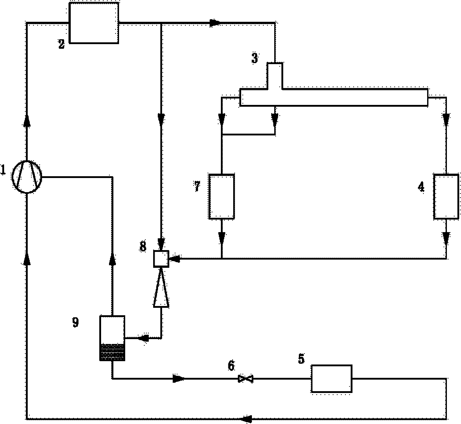
[0023] see figure 1 , figure 1 It is a flow diagram of an embodiment of the system of the present invention, and the refrigeration system includes a compressor 1, a first condenser 2, a vortex tube 3, a second condenser 4, a first evaporator 5, and a first throttle valve 6. The second evaporator 7, the first injector 8, and the gas-liquid separator 9. The outlet of the compressor 1 is connected with the inlet of the first condenser 2, and the outlet of the first condenser 2 is divided into two paths, one path is connected with the inlet of the vortex tube 3, and the other path is connected with the working fluid inlet of the first ejector 8, and the vortex After the gas outlet of the cold end of the tube 3 merges with the liquid outlet of the vortex tube 3, it is connected to the inlet of the second evaporator 7, the outlet of the hot end of the vortex tube 3 is connected to the inlet of the second condenser 4, and the outlet of the second condenser 4 is connected to the seco...

Embodiment 2

[0043] see Figure 4 , Figure 4 It is a schematic flow chart of another embodiment of the system of the present invention. The refrigeration system includes a compressor 1, a first condenser 2, a vortex tube 3, a second condenser 4, a first evaporator 5, and a first throttle valve 6. The second evaporator 7 , the first injector 8 , the gas-liquid separator 9 , the second injector 10 , the third evaporator 11 , and the second throttle valve 12 . The outlet of the compressor 1 is connected with the inlet of the first condenser 2, and the outlet of the first condenser 2 is divided into two paths, one path is connected with the inlet of the vortex tube 3, and the other path is connected with the working fluid inlet of the first ejector 8, and the vortex After the gas outlet of the cold end of the tube 3 is connected to the liquid outlet of the vortex tube 3, it is connected to the inlet of the second evaporator 7, the outlet of the hot end of the vortex tube 3 is connected to th...


PUM


Abstract

The invention discloses an ejector-based vortex pipe refrigeration system, which comprises a compressor, a first condenser, a vortex pipe, a second condenser, a first evaporator, a first ejector, a first throttle valve, a second evaporator and a gas-liquid separator. The compressor is sequentially connected with the first condenser and the vortex pipe in series; a hot end outlet of the vortex pipe is sequentially connected with the second condenser, the first ejector, the gas-liquid separator, the first throttle valve, the first evaporator and the compressor in series; and a cold end outlet of the vortex pipe is sequentially connected with the first ejector, the gas-liquid separator and the compressor in series. In the system the ejector is used to recycle energy of a refrigerant at the cold end outlet of the vortex pipe, so the refrigeration efficiency of the vortex pipe is improved; the condenser is arranged at the hot end outlet of the vortex pipe so that the throttling efficiency of the system is higher; and the single-temperature-level, two-temperature-level or multi-temperature-level refrigeration effect is achieved.

Description

technical field [0001] The invention relates to a refrigeration system, in particular to a multifunctional refrigeration system with an ejector and a vortex tube. Background technique [0002] In recent years, with the improvement of people's living standards and the global warming environment, people's demand for refrigeration systems is increasing. As the demand for refrigeration equipment increases, the energy consumption of the refrigeration system will increase as a proportion of the energy consumption of the entire society. This puts forward wider and higher requirements for the application range and work efficiency of the refrigeration system. [0003] In the traditional refrigeration system, the pressurized refrigerant expands through the throttle valve after passing through the condenser, and absorbs heat in the evaporator to produce refrigeration effect. The throttling valve has better performance for liquid throttling, but for gas throttling, its working efficien...

Claims


Application Information

Patent Timeline
IPC IPC(8): F25B9/04F25B9/08
Inventor 陈光明王征李涛韩晓红吴孔祥
Owner ZHEJIANG UNIV
Why Eureka
Try Eureka