
Multi-beam automatic scanning imaging method based on flexible ultrasonic array transducer

An ultrasonic array and scanning imaging technology, which is applied to the analysis of solids using sound waves/ultrasonic waves/infrasonic waves, can solve problems such as information loss, inability to realize interpolation scanning, and difficult ultrasonic reflection signals

Active Publication Date: 2013-03-06
BEIJING AERONAUTICAL MFG TECH RES INST
View PDF5 Cites 0 Cited by
  • Summary
  • Abstract
  • Description
  • Claims
  • Application Information

AI Technical Summary

Problems solved by technology

For ultrasonic penetration scanning imaging, single-channel scanning is mainly used; for reflection scanning imaging, in order to improve scanning imaging efficiency, ultrasonic phased array transducers are also used to realize multi-beam scanning, and ultrasonic phased array transducers use The overall mobile progressive scanning is mainly manual scanning. Due to the difficulty of surface contact coupling, low resolution, and large blind areas, it is currently difficult to popularize and apply it to engineering structures such as composite materials.
[0003] At present, the ultrasonic scanning method of large-scale structures such as composite materials is mainly based on the principle of single-beam scanning, and adopts a line-by-line scanning point-by-point detection method. For structures such as large-scale composite materials in industrial batch production, its obvious disadvantage is that the scanning efficiency is very low.
Another scanning method is based on the ultrasonic phased array method, which realizes multi-beam scanning to improve scanning efficiency. The complex engineering structure makes it difficult to achieve effective and reliable acoustic coupling; (b) it is difficult to realize ultrasonic automatic scanning of structures such as large composite materials, and the resolution and surface detection blind area is large (generally around 1mm); Complementary scan
[0004] The results of the current reflective ultrasonic automatic scanning imaging method for composite materials and other structures show that one-dimensional information (such as amplitude signal) is mainly used for imaging, and its obvious disadvantage is: for non-equal thickness structures, it is difficult to effectively distinguish between thickness changes It is difficult to effectively realize scanning imaging due to ultrasonic reflection signals caused by defects and defects. For many industrial fields such as aviation, the detected engineering structures are mainly of variable thickness. This method of acoustic beam scanning imaging is almost difficult to achieve correct scanning imaging display.
However, the shortcomings of the ultrasound beam scanning imaging method are: the depth information of the defects in the detected parts cannot be obtained, the detection sensitivity and resolution are not as high as the reflection method, and it is difficult to realize the ultrasonic penetration method for the overall structure such as composite materials. Scanning imaging, and scanning imaging efficiency is low
[0005] The results of existing ultrasonic scanning imaging methods are mainly displayed on computer monitors. The actual large-scale structures such as composite materials to be detected are often much larger than the display area of ​​computer physical monitors, and the amount of information for ultrasonic detection of large-scale structures such as composite materials is often It is also very large, using the traditional compressed imaging display method, the information loss is serious, and it is easy to cause the display to be missed

Method used


Image

  • Multi-beam automatic scanning imaging method based on flexible ultrasonic array transducer
  • Multi-beam automatic scanning imaging method based on flexible ultrasonic array transducer
  • Multi-beam automatic scanning imaging method based on flexible ultrasonic array transducer

Examples


Embodiment Construction

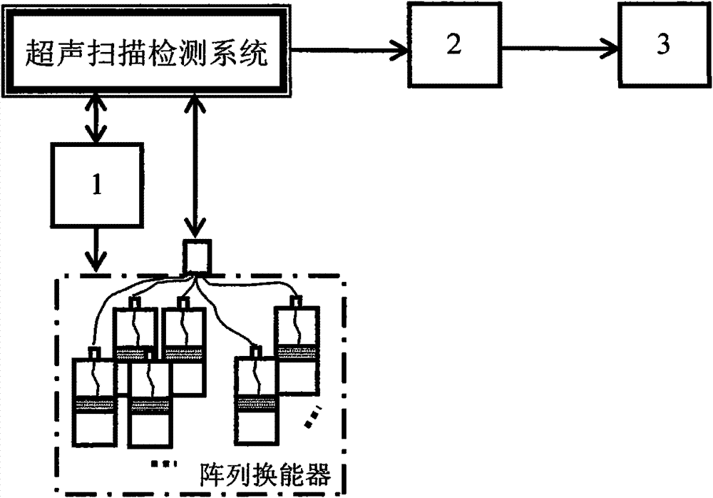
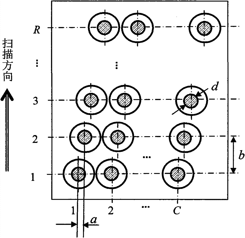
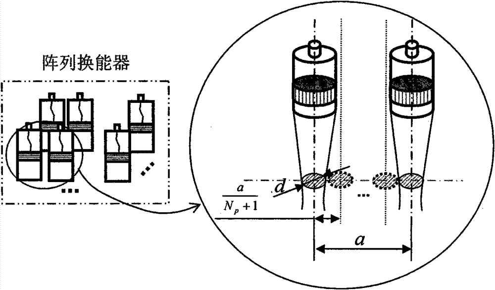
[0045] The method of the present invention is to use the ultrasonic detection system to control the ultrasonic array transducer to perform multi-sound beam automatic interpolation scanning, extract the multi-sound beam scanning position information and ultrasonic information in real time through the ultrasonic detection system, and generate Multi-beam scanning imaging information, establish the virtual mapping relationship between the geometric position of the detected part and the imaging position, realize multi-beam automatic interpolation scanning imaging, and provide efficient, high-quality and fast ultrasonic multi-beam automatic interpolation scanning for large structures such as composite materials Imaging method. The realization of the method of the present invention mainly includes: multi-sound beam automatic interpolation scanning 1, multi-sound beam scanning imaging information extraction and reconstruction 2, multi-sound beam scanning imaging display 3 and several m...


PUM


Abstract

The invention belongs to the technical field of nondestructive testing and relates to a multi-beam automatic scanning imaging method based on a flexible ultrasonic array transducer. The method comprises the main process steps comprising multi-beam automatic interpolation scanning, multi-beam scanning imaging information extraction and reconfiguration, multi-beam scanning imaging display and the like. The method has the following beneficial effects: according to the combination of ultrasonic testing channels and the beam coverage rule, multimode multi-beam ultrasonic automatic interpolation scanning with different resolution ratios is realized, thus the ultrasonic scanning efficiency is manyfold improved and the surface testing dead zone and longitudinal resolution can reach about 0.15mm; the time domains and two-dimensional amplitude information which are generated by propagation of the ultrasonic waves in such structures as composites and the like are utilized to carry out scanning imaging; various information in the parts is reproduced through imaging; and the single valued mapping relationships between the imaging domains and the tested parts are established, thus realizing imaging display of the multi-beam automatic interpolation scanning testing result that such structures as large composites do not lose testing point information.

Description

technical field [0001] The invention belongs to the technical field of non-destructive testing, and relates to a multi-beam automatic scanning imaging method based on a flexible ultrasonic array transducer. Background technique [0002] Existing ultrasonic automatic scanning imaging methods for large-scale structures such as composite materials mainly use ultrasonic penetration and reflection methods, use the sound beam to scan the material or structure to be detected line by line, and then extract the ultrasonic signal of the detection position in each scanning line , according to the progressive scanning sequence and the position of the detection point, the detection result is imaged and displayed, and the ultrasonic scanning imaging is realized. Usually, the ultrasonic transducer is controlled by the ultrasonic testing equipment to scan the detected parts line by line and point by point according to the preset stepping amount and scanning speed. For ultrasonic penetratio...

Claims


Application Information

Patent Timeline
IPC IPC(8): G01N29/04G01N29/06
Inventor 刘松平刘菲菲李乐刚郭恩明李维涛白金鹏谢富原曹正华孟秋杰
Owner BEIJING AERONAUTICAL MFG TECH RES INST
Learn More