Striking-force test fixture for keyboard lines

A technology for testing fixtures and lines, which is applied in circuit breaker testing, and the measurement of balance force using force. Deformation, avoid wear and measurement center position change, improve the effect of accuracy

Active Publication Date: 2011-11-23
KUNSHAN JOING TECH
View PDF6 Cites 6 Cited by
  • Summary
  • Abstract
  • Description
  • Claims
  • Application Information

AI Technical Summary

Problems solved by technology

In this test, the machine can only test the upper limit of the percussion force of the keyboard circuit to be tested, but cannot complete the lower limit test of the percussion force, and the constant voltage 48V provided by the DC power supply makes the percussion force on the keyboard test point exceed 50g, generally far exceeding the required upper limit, the test is not accurate, for different test points, the upper limit of the knocking force cannot be adjusted according to the actual requirements; because the diameter of the iron shaft at the front end of the magnetic core of the solenoid valve Small and easy to bend, the bent iron shaft during the test causes the test rubber head to not be in the center of the test point, and due to the use of a tapered test rubber head, it is prone to wear and deformation during multiple tests, resulting in a smaller test contact surface and The test point deviates from the center position of the test point, resulting in inaccurate test results
In addition, the test splint on the test machine is driven by an air cylinder, which is prone to deviation and inaccurate positioning during the lifting process, which reduces the accuracy of the measurement results

Method used


Image

  • Striking-force test fixture for keyboard lines
  • Striking-force test fixture for keyboard lines
  • Striking-force test fixture for keyboard lines

Examples


Embodiment Construction

[0023] The structure of the present invention will be further described below in conjunction with the accompanying drawings.

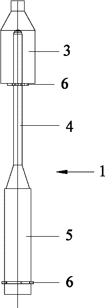
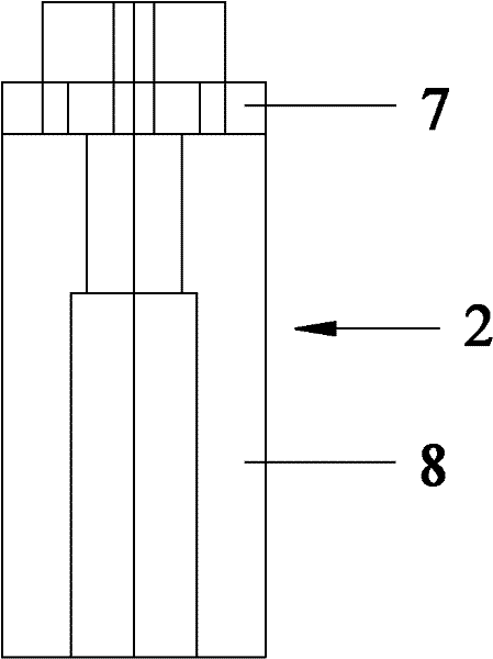
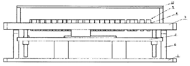
[0024] see figure 2 , 3 As shown, the keyboard circuit knocking force test fixture includes a base 1, a test table 2 horizontally arranged above the base 1 for supporting the keyboard circuit, a test splint 3 positioned above the test table 2 and horizontally arranged, and a test splint 3 set on the test splint 3 A perforation 4 extending vertically, a solenoid valve 5 fixedly inserted in the perforation 4, a power supply for supplying power to the solenoid valve 5, the solenoid valve 5 includes a hollow valve body 7 vertically inserted in the perforation 4, a vertical The magnetic core rod 8 directly inserted in the valve body 7 is connected to the valve body 7 by the power supply. The magnetic core rod 8 includes a thick rod part 9 and a thin rod part 10 distributed sequentially from top to bottom along the length direction of the rod. The pa...


PUM

PropertyMeasurementUnit
diameteraaaaaaaaaa
heightaaaaaaaaaa
heightaaaaaaaaaa

Abstract

The invention discloses a striking-force test fixture for keyboard lines, which is characterized in that an original electromagnetic valve tester is additionally provided with a baffle, and a power supply and an electromagnetic valve are replaced; when the striking-force test fixture for keyboard lines is used, through setting weights, a key point of a keyboard line is subjected to a striking-force lower limit test, then through energizing the electromagnetic valve, an electromagnetic force is produced for carrying out a striking-force upper limit test on the key point of the keyboard line, so that the weights of different weights and the energized voltage can be set and the length of a thick stem part of a spool stem in the electromagnetic valve can be adjusted according to different upper/lower limit requirements of a test point to be tested, thereby meeting the striking-force upper/lower limit test requirements of different test points; the declining height of a test fixture board is controlled through setting the baffle, so that the thin stem part of the spool stem on the electromagnetic valve is accurately positioned to a key point of a keyboard line to be tested; through enlarging the diameter of the thin stem part of the spool stem on the electromagnetic valve and directly pressing the spool stem against a product to be tested so as to directly carry out a striking-force test on the key point of the keyboard line, the bending or deformation of the thin stem part is avoided, and the abrasion caused by the application of a tapered test rubber head and the position change of a measuring center are avoided, thereby improving the measuring precision.

Description

[0001] technical field [0002] The invention relates to a fixture for testing the knocking force of keyboard lines. [0003] Background technique [0004] The existing solenoid valve testing machine includes a base, a test table top horizontally arranged on the base for supporting the keyboard line to be tested, a test splint horizontally placed above the test table, and a plurality of vertically extending bars on the test splint. A solenoid valve is fixed in the through hole. The solenoid valve includes a magnetic core 1, a solenoid valve body 2, a tapered test rubber head 3 and a spring (not shown in the figure), such as Figure 1-a As shown, the magnetic core 1 includes an iron needle 4, a carbon rod 5 and a circlip 6, and the iron needle 4 of the magnetic core 1 is covered with a tapered test rubber head, such as Figure 1-b As shown, the solenoid valve body 2 includes a nut 7, a cylinder body 8, a coil winding (not shown in the figure) and a lead wire (not shown in t...

Claims


Application Information

Patent Timeline
Patent Type & Authority Applications(China)
IPC IPC(8): G01R31/327G01L1/08
Inventor 邓龙升
Owner KUNSHAN JOING TECH
Why Eureka
Try Eureka