Unit-magnification multi-pass system optical path astigmatism compensation method and system thereof

A technology of magnification and compensation method, which is applied in optics, optical components, instruments, etc., can solve the problems of lack of theoretical methods for astigmatism compensation of UMS optical path, too limited analysis objects, and lack of versatility.

Inactive Publication Date: 2011-11-23
TSINGHUA UNIV
View PDF10 Cites 8 Cited by
  • Summary
  • Abstract
  • Description
  • Claims
  • Application Information

AI Technical Summary

Problems solved by technology

[0011] At present, the astigmatism compensation of the UMS optical path lacks a suitable theoretical method and due to the inconvenience of modifying the software tracking, it is necessary to provide an initial value to achieve optimization in a small range, so there is no suitable numerical calculation method.
The research results of researchers on astigmatism analysis and compensation methods often have poor astigmatism compensation effects and too much restrictions on the analysis object, lack of versatility, low precision, and it is difficult to provide strong help for UMS optical path optimization. In the astigmatism analysis compensation method, it is difficult to directly use ray tracing software to perform astigmatism compensation on the UMS optical path

Method used


Image

  • Unit-magnification multi-pass system optical path astigmatism compensation method and system thereof
  • Unit-magnification multi-pass system optical path astigmatism compensation method and system thereof
  • Unit-magnification multi-pass system optical path astigmatism compensation method and system thereof

Examples


Embodiment 1

[0171] BHWC light path

[0172] Such as Figure 4 The basic parameters of the BHWC optical path shown in -1 are R=625mm, p=40mm, h=20mm, Δ=50mm and n=40, and its numerical aperture is NA=0.05. When no compensating spherical mirror is used for compensation, the calculated astigmatism is 24.8mm. At this time, the imaging (Media focus) spot diagram of the 5 field points (0, 0), (±0.5, 0) and (0, ±0.5) in the field of view of the object is as follows Figure 10 , the scale bar is 2000 μm, and its RMS radius is 450-480 μm.

[0173] A spherical mirror with a radius of curvature r=200mm is used as the compensation spherical mirror, and the structure diagram of the system after compensation is as follows Figure 11 As shown, the numerical aperture of the system remains unchanged at 0.05, that is, a=1. The parameters of the compensation spherical mirror are shown in Table 1. At this time, the imaging light spot diagram of the 5 field points (0, 0), (±0.5, 0) and (0, ±0.5) in the f...

Embodiment 2

[0175] Improved White optical path with variable optical length

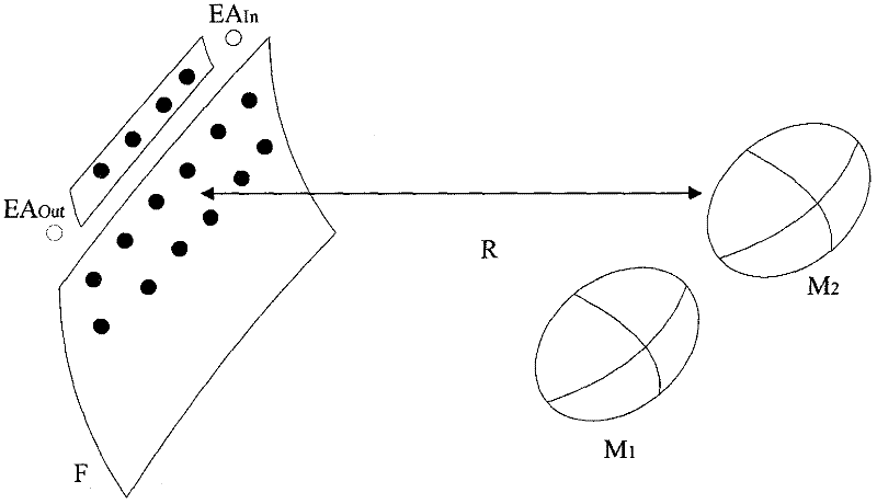
[0176] Such as Figure 2-3 As shown, it is an improved White light path with 96 light paths. Among them, F 1 is a field mirror, and the center of curvature is C F ; 1 and M 2 are two spherical objectives whose centers of curvature are C 1 and C 2 ;EA In Indicates the input aperture; EA Out Indicates the output aperture. ①~ In turn is the imaging spot of the input aperture on the surface of the field mirror. For the convenience of parameter description, in the schematic diagram, a three-dimensional Cartesian coordinate system X is established r -Y r -Z r , whose origin is O. C F and center vertices are at Z r on axis, C 1 and C 2 in Y r on axis.

[0177] For a BHWC optical path whose optical path number is n (n is a multiple of 4), C F The coordinates are (0, 0, R), C 1 and C 2 They are (0, c / 2, 0) and (0, -c / 2, 0), respectively, c=4p / n. The distance between two rows of imaging spots ente...


PUM


Abstract

The invention provides a unit magnification multi-pass system optical path astigmatism compensation method and a system thereof, and belongs to the field of astigmatism compensation of a unit magnification multi-pass system. The method is characterized in that: a compensation spherical mirror is introduced behind an output aperture of a UMS (unit magnification multi-pass system) optical path which at least comprises a White optical path, various improved White optical paths and an MMS (multi-pass matrix system) optical path, the compensation spherical mirror and the whole astigmatism of the UMS optical path are compensated by adjusting the radium of the compensation mirror and the beam full divergence angle adjustment parameters, the output beam of the UMS optical path is reflected on the compensation spherical mirror, the transmission meridian plane of the compensation spherical mirror is possibly superposed with the sagittal plane of the output beam of the UMS optical path, and the astigmatism of the compensation spherical mirror is the same as that of the output beam of the UMS optical path with opposite directions, so that the astigmatism is compensated, and the divergence angle of the output beam can be further adjusted to match with the numerical aperture of a subsequent optical path.

Description

technical field [0001] The invention belongs to a follow-up astigmatism compensation optical path structure of a unit magnification multi-path optical path (UMS optical path, Unit-magnification Multi-pass System). This optical path structure has an astigmatism compensation function and is suitable for unit amplification in an optical detection system. The astigmatism compensation of the magnification multi-path optical path is especially suitable for the optical cavity in the field of gas detection. Background technique [0002] Common light sources with large beam divergence angles can be used in White optical path, improved White optical path (improved White optical path), and multi-pass matrix system (MMS: Multipass Matrix System). These three types of optical paths are multi-light It is the first choice for long-range absorption spectroscopy systems and has been widely used in trace gas detection systems. These optical paths have the same characteristics: they are mainl...

Claims


Application Information

Patent Timeline
Patent Type & Authority Applications(China)
IPC IPC(8): G02B27/00
Inventor 杨怀栋陈科新许默涵孙利群何庆声金国藩
Owner TSINGHUA UNIV
Why Eureka
Try Eureka