Photoelectric conversion device and photoelectric conversion device module

A photoelectric conversion and device technology, applied in capacitor electrodes, electric solid devices, capacitor parts and other directions, can solve the problem of insufficient consideration, and achieve the effect of enhancing conversion efficiency, simple structure, and enhancing light collection efficiency

Inactive Publication Date: 2011-11-23
SONY CORP
View PDF4 Cites 4 Cited by
  • Summary
  • Abstract
  • Description
  • Claims
  • Application Information

AI Technical Summary

Problems solved by technology

However, in the solar cell modules described in Patent Document 7 and Patent Document 8, these needs are not sufficiently considered

Method used


Image

  • Photoelectric conversion device and photoelectric conversion device module
  • Photoelectric conversion device and photoelectric conversion device module
  • Photoelectric conversion device and photoelectric conversion device module

Examples


Embodiment

[0046]

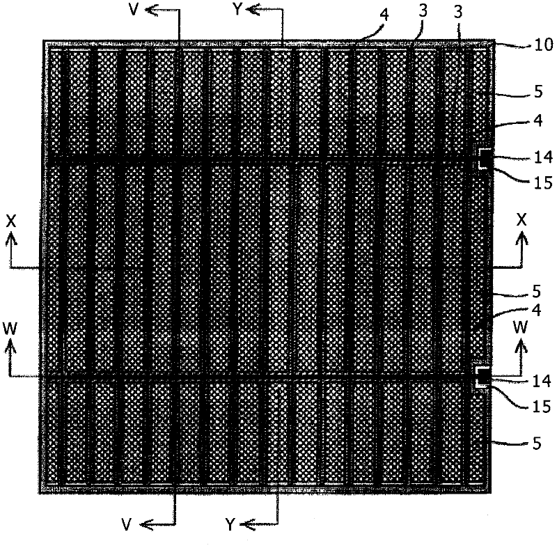
[0047] figure 1 It is a plan view for explaining the structure of the dye-sensitized solar cell (counter cell) in the example of the present invention.

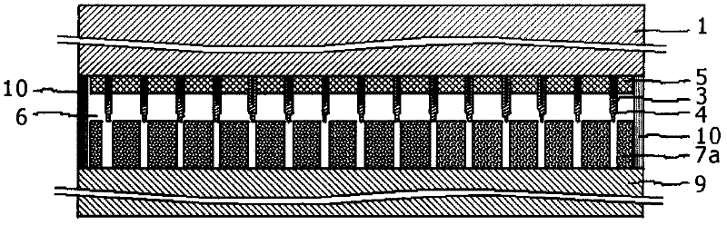
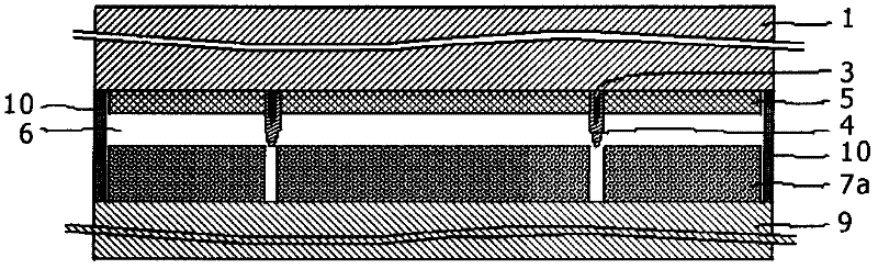
[0048] Figure 2A to Figure 2D is a cross-sectional view for explaining the structure of a dye-sensitized solar cell (counter cell) in an example of the present invention.

[0049] Figure 2A is along figure 1 The sectional view (X-X sectional view) taken by the shown X-X line. Figure 2B is along figure 1 The sectional view taken along the Y-Y line (Y-Y sectional view). Figure 2C is along figure 1 The sectional view taken along the line W-W shown (W-W sectional view). Figure 2D is along figure 1 The sectional view taken along the line V-V shown (V-V sectional view).

[0050] Such as figure 1 with Figures 2A-2D As shown, the opposite unit is composed of a window electrode (working electrode), an opposite electrode and an electrolytic layer 6, the light is incident on the window electrode, the opposite...


PUM

PropertyMeasurementUnit
thicknessaaaaaaaaaa
widthaaaaaaaaaa
lengthaaaaaaaaaa

Abstract

The present invention is to provide a photoelectric conversion device and photoelectric conversion device module, particularly a photoelectric conversion device including: a first substrate; a collector layer configured to be provided over the first substrate; a second substrate configured to be opposed to a planar surface of the first substrate and be formed of a metal having a concave notch part at one side; and a connection terminal configured to be connected to the collector layer. The connection terminal is disposed opposed to the concave notch part.

Description

technical field [0001] The present invention relates to a photoelectric conversion device and a photoelectric conversion device module obtained by arranging these photoelectric conversion devices in a plane and connecting them to each other. Background technique [0002] In recent years, awareness of environmental protection is increasing, and the importance of photovoltaic power generation has further increased. In a dye-sensitized solar cell (DSSC), a transparent conductive layer and an oxide semiconductor layer are formed over a transparent substrate, and the oxide semiconductor layer obtained by carrying a sensitizing dye, carrying The oxide semiconductor layer (photoelectric conversion layer) of the fuel is used as a working electrode (photoelectrode, window electrode). In addition, a redox electrolytic layer is arranged between the working electrode and the opposing electrode. In this fuel-sensitized solar cell, electrons excited by sunlight in the dye are injected i...

Claims


Application Information

Patent Timeline
Patent Type & Authority Applications(China)
IPC IPC(8): H01G9/004H01G9/04H01G9/20H01G9/26H01M14/00H01L51/44
CPCH01G9/2059H01G9/2081H01G9/20Y02E10/542H01M14/00H01G9/2031Y02E10/50H01L31/05H01L31/035281Y02P70/50
Inventor 诸冈正浩多田圭志
Owner SONY CORP
Why Eureka
Try Eureka