
Method for reducing line edge roughness (LER) and device for implementing method

A semiconductor and feature structure technology, applied in semiconductor devices, electrical components, circuits, etc., can solve problems such as the control of device leakage current and short-channel effect, and affect device performance, so as to avoid device performance degradation and avoid threshold voltage. changes, the effect of increasing the signal-to-noise ratio

Active Publication Date: 2011-11-23
BEIJING NAURA MICROELECTRONICS EQUIP CO LTD
View PDF4 Cites 6 Cited by
  • Summary
  • Abstract
  • Description
  • Claims
  • Application Information

AI Technical Summary

Problems solved by technology

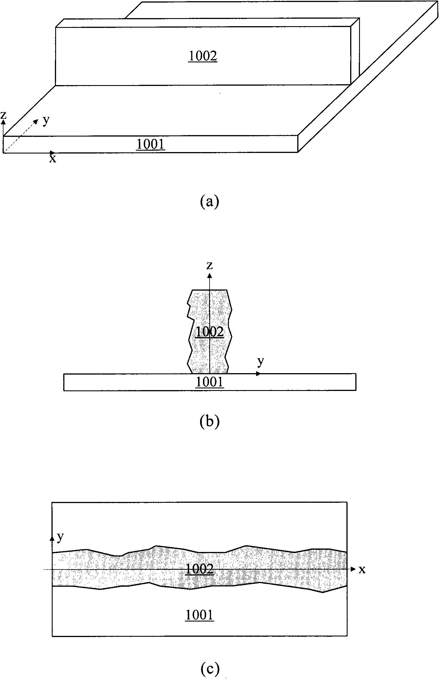
In addition, etch processes used in lithography, such as plasma etch, can also cause LER in features
[0005] This LER present in the characterization will ultimately affect the performance of the device
For example, if there is LER when forming the gate, it will greatly affect the control of off-state leakage current and short channel effect of the device

Method used


Image

  • Method for reducing line edge roughness (LER) and device for implementing method
  • Method for reducing line edge roughness (LER) and device for implementing method
  • Method for reducing line edge roughness (LER) and device for implementing method

Examples


Embodiment Construction

[0021] Hereinafter, the present invention is described by means of specific embodiments shown in the drawings. It should be understood, however, that these descriptions are exemplary only and are not intended to limit the scope of the present invention. Also, in the following description, descriptions of well-known structures and techniques are omitted to avoid unnecessarily obscuring the concept of the present invention.

[0022] A schematic diagram of a layer structure according to an embodiment of the invention is shown in the drawing. The figures are not drawn to scale, with certain details exaggerated and possibly omitted for clarity. The shapes of the various regions and layers shown in the figure, as well as their relative sizes and positional relationships are only exemplary, and may deviate due to manufacturing tolerances or technical limitations in practice, and those skilled in the art will Regions / layers with different shapes, sizes, and relative positions can be...


PUM


Abstract

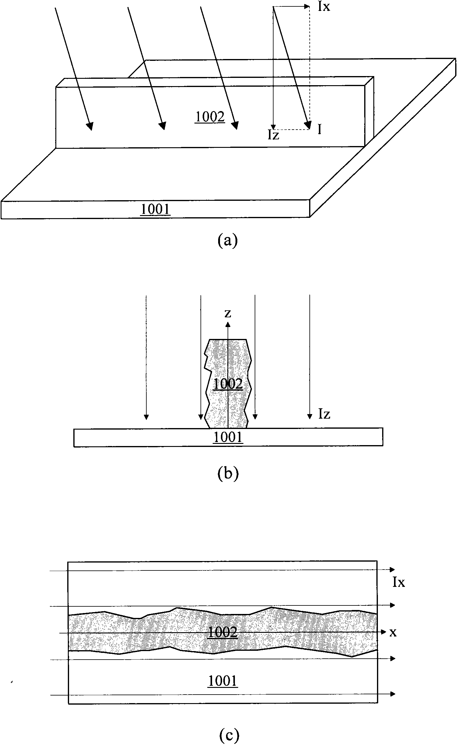
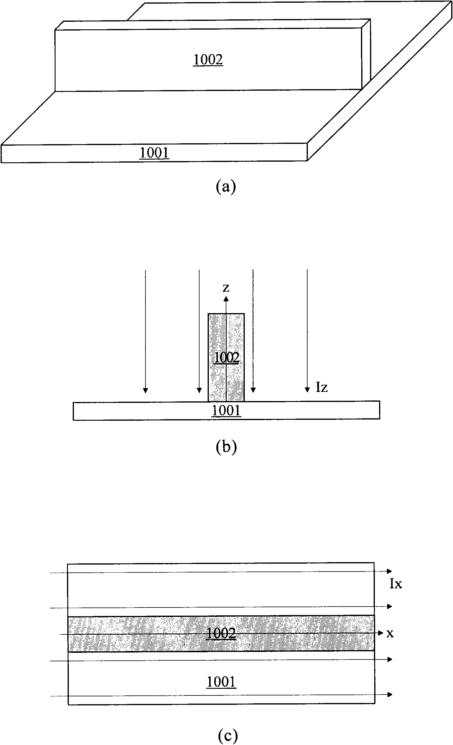
The invention discloses a method for reducing line edge roughness (LER) and a device for implementing the method. The method comprises the following steps of: providing a semiconductor substrate; forming a semiconductor device on the semiconductor substrate, wherein the semiconductor device comprises a specific feature structure; and performing ion / plasma etching on the specific feature structure in a mode of being parallel to the direction of the specific feature structure and forming an inclined angle with the surface of the semiconductor substrate. Therefore, the performance deterioration of the device caused by the LEF can be effectively reduced.

Description

technical field [0001] The present application relates to the field of semiconductor manufacturing technology, and more specifically, to a method for reducing line edge roughness (Line Edge Roughness, LER) of a feature structure formed in a semiconductor device and a device for implementing the method. Background technique [0002] With the development of technology, the integration density on integrated circuits is increasing day by day. To achieve this high level of integration, device features are getting smaller and smaller. Such features include, for example, connection lines, functional regions, etc. formed in the semiconductor device. [0003] In order to realize such small-scale features, a high-resolution photolithography process is required. However, as the feature size (eg, line width) decreases, a problem known as "line edge roughness" (LER) is encountered. The so-called LER refers to the degree of irregularity at the edge or sidewall of a feature structure fo...

Claims


Application Information

Patent Timeline
Patent Type & Authority Applications(China)
IPC IPC(8): H01L21/3065H01L21/28H01L21/00
Inventor 骆志炯尹海洲朱慧珑
Owner BEIJING NAURA MICROELECTRONICS EQUIP CO LTD
Learn More