
Brushless permanent magnet direct current motor for automobile

A permanent magnet DC, automotive technology, applied in electrical components, electromechanical devices, magnetic circuit static parts, etc., can solve the problems affecting the reliability and life of the motor, many contacts, and large installation space, to ensure electrical safety performance. and the effect of product quality requirements, simplified controllers, and improved reliability

Inactive Publication Date: 2011-11-23
WUXI SOUTHEAST VEHICLE TECH
View PDF4 Cites 0 Cited by
  • Summary
  • Abstract
  • Description
  • Claims
  • Application Information

AI Technical Summary

Problems solved by technology

[0002] At present, the fan for automobiles adopts a brushed DC motor with a power of 90W-800W. The structure of the motor includes a stator, a rotor with a commutator, and a brush holder assembly. The brush holder assembly includes carbon brushes, springs, brush houses, In the vibration reduction part, the structure of the commutator and the carbon brush is complex, and the installation space is large, and the contact resistance of the commutator and the carbon brush of the brushed DC motor is very large, which affects the reliability and life of the motor, and the efficiency is low
[0003] Now the industry adopts DC brushless motors. DC brushless motors have good reliability and are suitable for use in automotive fans. In order to simplify the structure, a Hall-free control method is usually used, but a motor without Hall control needs to be equipped with a controller, and The internal circuit of the controller is complicated, there are many contacts, and the reliability is difficult to guarantee. Moreover, when the controller controls the motor to rotate, it needs to be equipped with a special circuit for the initial rotation direction of the rotor, which also increases the complexity of the controller.

Method used


Image

  • Brushless permanent magnet direct current motor for automobile
  • Brushless permanent magnet direct current motor for automobile
  • Brushless permanent magnet direct current motor for automobile

Examples


Embodiment Construction

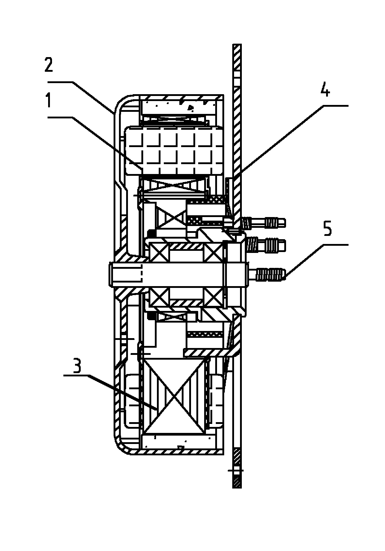
[0017] See figure 1 , Figure 5 As shown, the present invention includes a stator 1, an outer rotor 2, and an insulation system 3. The insulation system 3 includes a stator core 12, an insulation board, and an outlet socket 9. An insulation plug is placed between the stator core 12 and the polyester enameled round copper wire. plate, and 4 is the fixed plate.

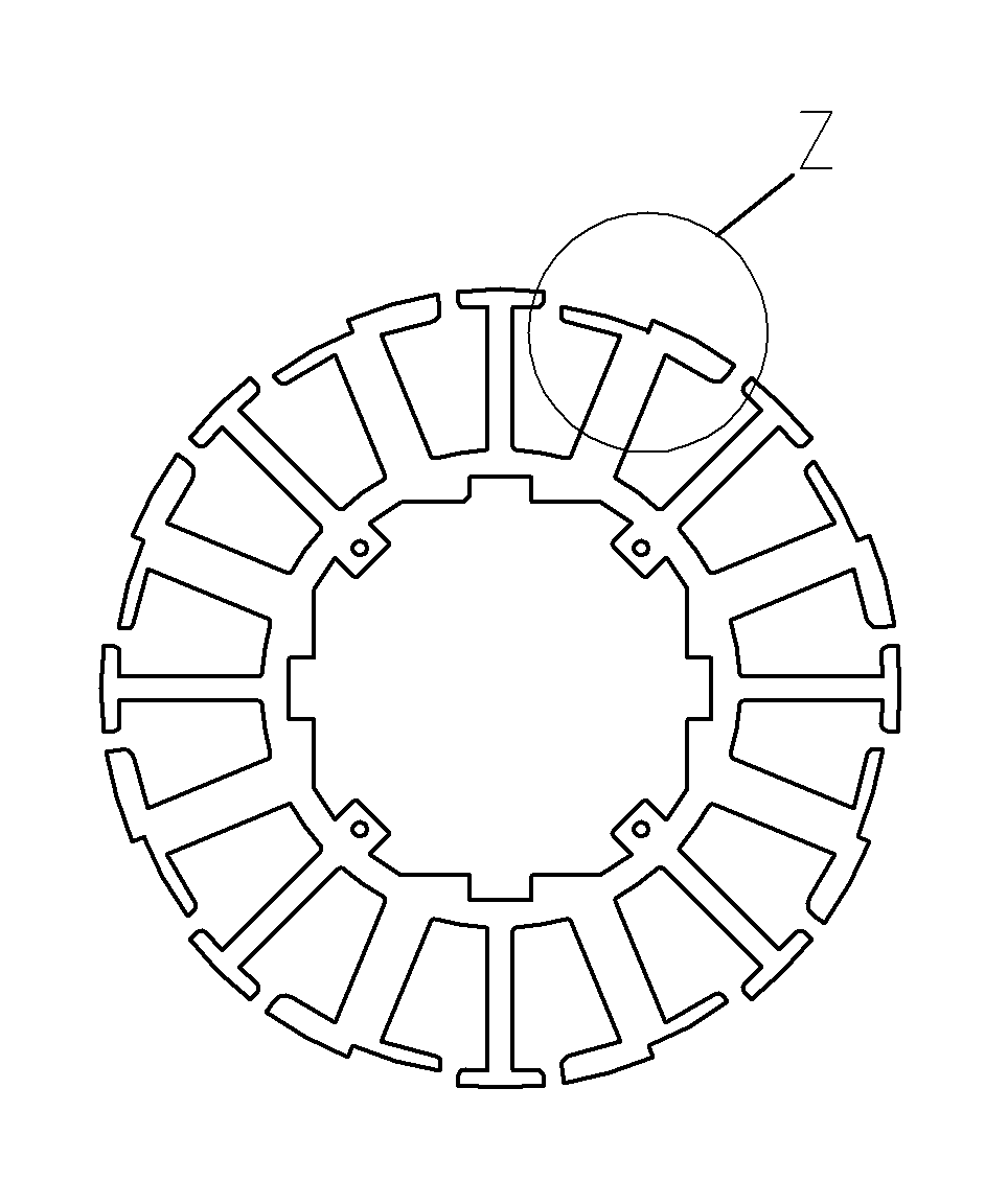
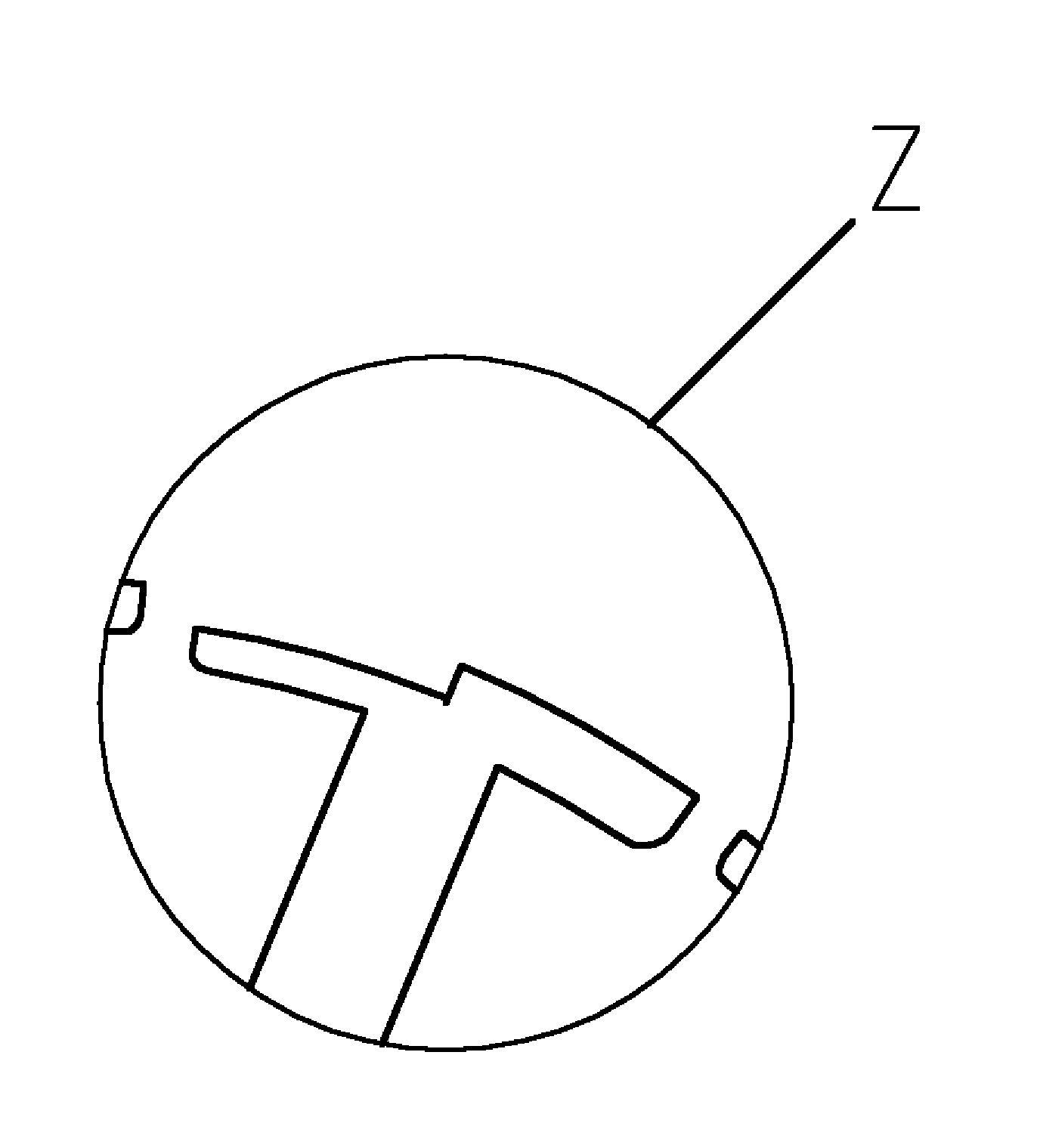
[0018] See figure 2 , image 3 and Figure 5 As shown, a magnetic field equivalent to a rotating magnetic field is designed to be established in the magnetic field, and a gap is designed in the T-shaped tooth portion of the stator 1 according to the magnetic circuit, so that the distribution of the air gap between the stator 1 and the outer rotor 2 is not uniform, and the magnetic field strength and torque are generated. Therefore, a rotating magnetic field is generated, and the outer rotor 2 is fixed to rotate in the direction of the gap, which improves the reliability of the brushless permanent magnet DC motor an...


PUM


Abstract

The invention provides a brushless permanent magnet direct current motor for an automobile. The brushless permanent magnet direct current motor has a compact and reasonable structure. A controller has a good controlling effect, a rotor rotates in a predetermined direction, and high reliability is achieved. The brushless permanent magnet direct current motor comprises a stator, an outer rotor and an insulating system, and is characterized in that: the circular-arc top surface of a T-shaped toothed part of the stator is provided with a gap according to a magnetic path; and a rotating magnetic field is formed around the gap.

Description

technical field [0001] The invention relates to a brushless permanent magnet DC motor in electrical technology, in particular to a brushless permanent magnet DC motor for automobiles. Background technique [0002] At present, automotive fans use brushed DC motors with a power of 90W-800W. The structure of the motor includes a stator, a rotor with a commutator, and a brush holder assembly. The brush holder assembly also includes carbon brushes, springs, brush houses, In the vibration damping part, the commutator and the carbon brush have a complex structure and a large installation space, and the contact resistance between the commutator and the carbon brush of the brushed DC motor is large, which affects the reliability and life of the motor, and the efficiency is low. [0003] At present, brushless DC motors and brushless DC motors are used in the industry. They have good reliability and are suitable for automotive fans. In order to simplify the structure, Hall-free control...

Claims


Application Information

Patent Timeline
Patent Type & Authority Applications(China)
IPC IPC(8): H02K29/00H02K1/14H02K3/34
Inventor 钱东高陈春荣
Owner WUXI SOUTHEAST VEHICLE TECH
Learn More