Pressure booster and diecasting arrangement

A converter and pressure technology, applied in the direction of fluid pressure converter, fluid pressure actuating device, servo meter circuit, etc., can solve the problems of failure of spring preloading device, obstructed flow cross section, high production cost, etc., and achieve operation capacity. Strong, simple structure principle, the effect of improving operational safety and mechanical reliability

Active Publication Date: 2011-11-23
BUHLER DRUCKGASS AG
View PDF5 Cites 6 Cited by
  • Summary
  • Abstract
  • Description
  • Claims
  • Application Information

AI Technical Summary

Problems solved by technology

[0003] The known solution is characterized by an obstructed flow section and relatively high production costs
In addition, the spring preloading device usually used in the check valve has the risk of failure.

Method used


Image

  • Pressure booster and diecasting arrangement
  • Pressure booster and diecasting arrangement
  • Pressure booster and diecasting arrangement

Examples


Embodiment Construction

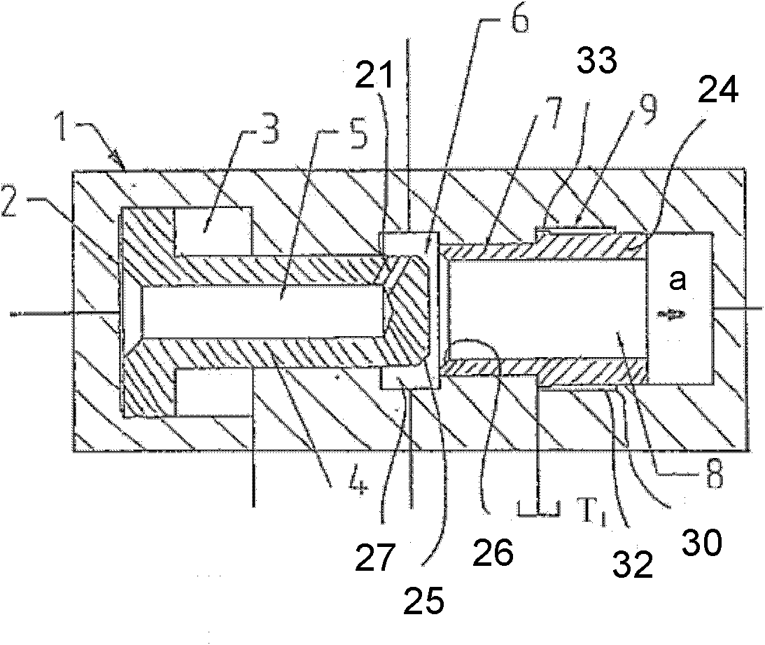
[0035] figure 1 Shows a pressure converter labeled 1, which can be used to increase the pressure in the piston chamber of a working fluid cylinder (not shown here). A pressure converter of this kind can be installed in an injection machine or press, for example.

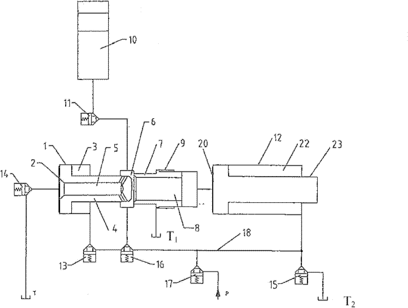
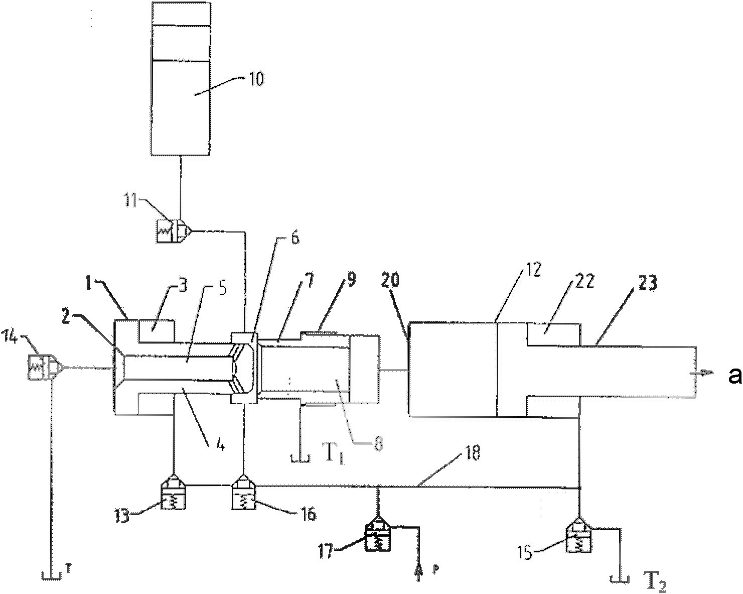
[0036] In order to be integrated in a device of the injection machine, different pipelines can be provided. in figure 1 The simplification of the interface for the input and output of hydraulic medium is shown with thin lines. In relation to the substantially annular liquid inlet chamber arranged in the middle, for example, two ports can be seen to the pressure medium supply device. Each interface and the parts connected to it are shown in the following appendix Figure 2 to 6 Inside and explained. The pressure converter 1 has a pressure converter piston 4, which consists of a piston part and a piston rod coaxially connected to it. Visibly, the diameter of the piston part is larger than the diameter of the piston rod...


PUM


Abstract

A pressure booster (1) for a diecasting machine comprises a pressure booster piston (4) having a valve seat (7), wherein the pressure booster piston (4) interacts with the valve seat (7) to form a shut-off or non-return valve (6). The valve body (24) is displaceable to a limited extent in the axial direction (a) and can be retained hydraulically in a starting position. (Figure 1)

Description

Technical field [0001] The invention relates to a pressure transducer according to the preamble of claim 1, in particular a pressure transducer in a drive device of an injection machine. The invention also relates to a device for injecting with such a pressure converter and a working- or injecting liquid cylinder. But the pressure converter can also be used in the drive of a press or other working machine. Background technique [0002] Pressure converters have a pressure converter piston and an integrated check valve or an external bypass check valve, which have been well known and commonly used for a long time. One such one-way valve prevents the hydraulic medium from returning from a high pressure chamber of a load to the piston chamber of the pressure converter. For example, from DE 1 949 360 A, a pressure converter is known which has a check valve integrated in the pressure converter piston. [0003] The known solutions are characterized by an obstructed flow profile and rel...

Claims


Application Information

Patent Timeline
Patent Type & Authority Applications(China)
IPC IPC(8): B22D17/32B22D17/20
CPCF15B2211/214F15B3/00B22D17/2069B22D17/32
Inventor D·豪瑟
Owner BUHLER DRUCKGASS AG
Why Eureka
Try Eureka