
Double cantilever large deformation strain measurement sensor

A technology of strain measurement and large deformation, applied in the direction of electric/magnetic solid deformation measurement, electromagnetic measurement device, etc., to achieve the effects of high sensitivity, reasonable design, high anti-interference ability and stability

Inactive Publication Date: 2011-11-30
CHANGAN UNIV
View PDF7 Cites 9 Cited by
  • Summary
  • Abstract
  • Description
  • Claims
  • Application Information

AI Technical Summary

Problems solved by technology

[0004] The technical problem to be solved by the present invention is to overcome the shortcomings of the above-mentioned double-cantilever concrete structure strain gauge, and provide a strain gauge with reasonable design, high sensitivity, easy calibration, small linear error, strong anti-interference ability, good stability, adjustable gauge length, Widely applicable double cantilever large deformation strain measurement sensor

Method used


Image

  • Double cantilever large deformation strain measurement sensor
  • Double cantilever large deformation strain measurement sensor
  • Double cantilever large deformation strain measurement sensor

Examples


Embodiment 1

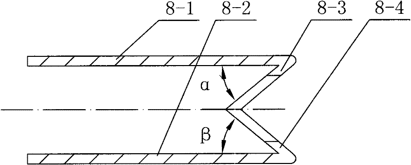
[0022] exist figure 1 Among them, the double cantilever large deformation strain measurement sensor of this embodiment consists of a left end connecting rod 1, a left end support 2, a left end compression butterfly screw 3, a fixed body 4, a centering limit slide rod 5, a resistance strain gauge 6, and a balance spring 7, spring leaf 8, sleeve 9, wedge-shaped body 10, silicon rubber ring 11, right end compression butterfly screw 12, right end bearing 13, right end connecting rod 14 are connected and constituted.

[0023] On the left end support 2, use the left end to compress the butterfly screw 3 to fix the connection and install the left end connecting rod 1 arranged horizontally. The fixed body 4 of example is a boss-shaped structure, a sleeve 9 is fixedly installed on the left end of the fixed body 4, and a spring leaf 8 is fixedly connected and installed on the right end boss of the fixed body 4 in the sleeve 9, and the shape of the spring leaf 8 is W-shaped. , the left ...

Embodiment 2

[0026] In the embodiment, the angle α between the upper plane plate 8-3 and the upper plane 8-1 is 20°, and the angle β between the lower plane plate 8-4 and the lower plane 8-2 is 20° , the positions of the rectangular through hole a on the upper plane plate 8-3 and the lower plane plate 8-4 are the same as those in Embodiment 1. Other components and the coupling relationship of the components are the same as in Embodiment 1.

Embodiment 3

[0028] In the embodiment, the included angle α between the upper flat plate 8-3 and the upper flat plate 8-1 is 70°, and the included angle β between the lower flat plate 8-4 and the lower flat plate 8-2 is 70° , the positions of the rectangular through hole a on the upper plane plate 8-3 and the lower plane plate 8-4 are the same as those in Embodiment 1. Other components and the coupling relationship of the components are the same as in Embodiment 1.


PUM

PropertyMeasurementUnit
Thicknessaaaaaaaaaa
Angleaaaaaaaaaa
Thicknessaaaaaaaaaa

Abstract

The invention relates to a two-cantilever large-deformation strain measurement sensor. A left end holder is provided with a left end connecting rod, a right end holder is provided with a right end connecting rod, the right end of the left end connecting rod is provided with a fixing body mounted at the left end in a sleeve, the left end of the right end connecting rod is provided with a wedge-shaped body mounted at the right end in the sleeve, the right end of the fixing body in the sleeve is provided with a spring leaf and a centering / spacing slide rod positioned in the spring leaf, the centering / spacing slide rod is externally provided with a compensating spring, the right end of the centering / spacing slide rod is arranged on the wedge-shaped body, the spring leaf is provided with even-numbered (at least four) resistance strain gages, and all the resistance strain gages form a full bridge which uses a lead wire for output. By using the W-shaped spring leaf, the invention greatly improves the sensitivity; and as both ends of the spring leaf are fixed, the two-cantilever large-deformation strain measurement sensor can still have high antijamming capability and stability even if the external loading force changes a lot. The two-cantilever large-deformation strain measurement sensor provided by the invention has the advantages of high sensitivity, easy calibration process, less linearity error, high antijamming capability, good stability and the like, and can be used as a large-deformation displacement sensor.

Description

technical field [0001] The invention belongs to the technical field of equipment for measuring relative displacement, and in particular relates to a double cantilever large deformation displacement sensor. Background technique [0002] In the field of engineering, it is often necessary to study the large deformation of materials and structures. For example, when studying the mechanical properties of engineering materials, when the material yields, its relative deformation is relatively large. At present, the commonly used measurement method is to use plastic strain gauges directly Pasted on the test piece, due to the influence of many factors such as the pasting technology, the performance of the strain gauge, the performance of the glue used for the patch, the ambient temperature and the ambient humidity, the measurement effect is often very unsatisfactory. In addition, when studying the mechanical properties of masonry structures, it is necessary to measure the deformation...

Claims


Application Information

Patent Timeline
IPC IPC(8): G01B7/16
Inventor 王建华胡大琳任更峰陈凤翔韩学坤赵艳峰张治军
Owner CHANGAN UNIV
Learn More