Disposable uncovered holographic electronic tag antenna and its manufacturing method and application

A technology of electronic tags and manufacturing methods, applied to antennas, antenna parts, antenna supports/installation devices, etc., to achieve the effects of increasing aesthetics, reducing costs, and simplifying manufacturing processes

Active Publication Date: 2011-11-30
SHANDONG TAIBAO PREVENTING COUNTERFEIT
View PDF9 Cites 7 Cited by
  • Summary
  • Abstract
  • Description
  • Claims
  • Application Information

AI Technical Summary

Problems solved by technology

[0013] (3) Impedance

Method used


Image

  • Disposable uncovered holographic electronic tag antenna and its manufacturing method and application
  • Disposable uncovered holographic electronic tag antenna and its manufacturing method and application
  • Disposable uncovered holographic electronic tag antenna and its manufacturing method and application

Examples


Embodiment 1

[0045] Example 1, a disposable holographic electronic tag antenna made of fragile paper and applied to RFID:

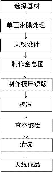
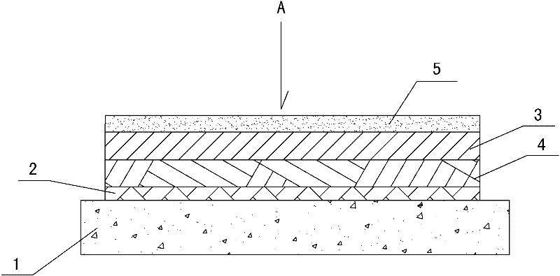
[0046] (1) Choose fragile paper as the substrate layer (thickness 0.5mm ~ 2.5mm), and coat one side of the substrate layer to ensure the smoothness of the processed surface suitable for the antenna to form the antenna processed surface.

[0047] (2) Preparation of antenna holographic layer:

[0048] a. Antenna design: UHF2.45GHZ antennas are made according to customer requirements. The reading distance is 10-15m; The impact of the actual half-wave dipole antenna is required to be 57mm in length, the antenna input impedance is about 72Ω, the impedance bandwidth is 14.3% when the voltage standing wave ratio (VSWR) is less than 2.0, and the antenna gain is 1.8.

[0049] b. Make a hologram: According to the designed antenna size and shape, take an information map of the antenna. This information map is the master plate for making a hologram. It is composed of dense, intr...

Embodiment 2

[0060] Example 2: Disposable uncovered holographic electronic tag antenna for RFID made of polyester film:

[0061] (1) Select polyester film as the substrate layer (thickness 0.6-1.6mm), and perform coating treatment on one side of the substrate layer to ensure the smoothness of the processing surface suitable for the antenna to form the antenna processing surface.

[0062] The steps of (2) preparing the antenna hologram layer, (3) vacuum aluminum plating and (4) cleaning are the same as in Example 1.

[0063] (5) Product inspection:

[0064] Test results: When the chip used in the antenna is at 915MHZ, the external impedance is Z=18.1-j149Ω. In order to realize the maximum power transmission between the tag chip and the tag antenna, the antenna impedance should be 18.1+j149Ω at the resonant frequency. When the standing wave ratio is less than 2, the bandwidth is 218MHz (802MHz ~ 1.02GHz), which meets the design requirements of UHF frequency band, and the relative bandwidth ...

Embodiment 3

[0065] Example 3: Disposable uncovered holographic electronic tag antenna for RFID made of coated paper:

[0066] (1) Select coated paper as the substrate layer (thickness 1.6mm), and coat one side of the substrate layer to ensure the smoothness of the processed surface suitable for the antenna to form the processed surface of the antenna.

[0067] The steps of (2) preparing the antenna hologram layer, (3) vacuum aluminum plating and (4) cleaning are the same as in Example 1.

[0068] (5) Product inspection:

[0069] Test results: When the chip used in the antenna is at 2.45GHZ, the input impedance of the antenna is 75Ω, the impedance bandwidth is 14.3% when the voltage standing wave ratio is less than 2, and the antenna gain is 1.8. For most RFID application systems, the antenna can meet Require.


PUM


Abstract

The invention belongs to the technical category of electronic label manufacturing, and specifically relates to a one-time uncovered holographic electronic label antenna and its manufacturing method and application, including a base material layer, and is characterized in that: a coating layer and an antenna hologram are sequentially arranged on the base material layer Layer and aluminized layer; the production method of the present invention includes preparing a substrate layer, preparing an antenna holographic layer, vacuum aluminizing, and cleaning; the application of the product obtained in the present invention in a disposable uncovered holographic electronic tag antenna. The invention uses polyester film, coated paper or fragile paper as a disposable substrate layer, which has the effect of anti-counterfeiting transfer and avoids being used for the second time; the manufacturing process is simplified, so that the holographic antenna can be printed in large quantities and quickly Replication can be used in combination with various printed materials, reducing costs; through the organic combination of holographic anti-counterfeiting and RFID technology, the aesthetics of the product is increased, and the anti-counterfeiting strength is improved.

Description

technical field [0001] The invention belongs to the technical category of electronic label manufacturing, and in particular relates to a one-time uncovered holographic electronic label antenna and a manufacturing method and application thereof. Background technique [0002] 1. Electronic tag technology: Electronic tag is RFID (Radio Frequency IDentifiication) technology, also known as radio frequency identification, which is a communication technology. The basic components of its system include RFID electronic tags, RFID readers and antennas. Among them, the antenna is a device that receives or radiates the radio frequency signal power of the radio transceiver in the form of electromagnetic waves. In the RFID system, the antenna is divided into two types: tag antenna and reader antenna. The goal of the tag antenna is to transmit the maximum energy into and out of the tag chip: when transmitting, convert high-frequency current into electromagnetic waves; when receiving, con...

Claims


Application Information

Patent Timeline
Patent Type & Authority Applications(China)
IPC IPC(8): H01Q1/00H01Q1/38H01Q1/12
Inventor 田少良巩建敏巩坤耿殿刚任慧颖
Owner SHANDONG TAIBAO PREVENTING COUNTERFEIT
Why Eureka
Try Eureka