Manufacturing method of metal-directly-plated RFID (radio frequency identification) electronic tag antenna

A production method and electronic label technology, applied in the structural form of radiation elements, can solve the problems of high cost and environmental pollution, and achieve the effects of reduced production cost, simple process and long production time

Active Publication Date: 2015-02-11
上海顺灏新材料科技股份有限公司
View PDF8 Cites 15 Cited by
  • Summary
  • Abstract
  • Description
  • Claims
  • Application Information

AI Technical Summary

Problems solved by technology

[0008] The purpose of the present invention is to provide a method for manufacturing RFID electronic tag antennas that can reduce the manufacturing cost of radio frequency antennas, is environmentally friendly, simple in process, and high in production efficiency, so as to overcome the high cost and environmental pollution of the existing electronic tag antenna manufacturing methods. and other shortcomings

Method used


Image

  • Manufacturing method of metal-directly-plated RFID (radio frequency identification) electronic tag antenna
  • Manufacturing method of metal-directly-plated RFID (radio frequency identification) electronic tag antenna

Examples


Embodiment 1

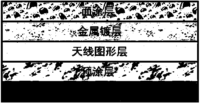
[0044] This embodiment provides an RFID film aluminum antenna, which is obtained through the following steps:

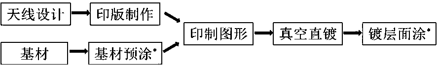
[0045] The substrate layer is PET film with a thickness of 20 μm; the shape and size of the antenna are designed according to the specific application requirements; according to the designed antenna pattern, laser engraving is made on the flexible printing plate to make a printing plate roll engraved with the antenna pattern; In the cavity of the vacuum coating machine, the direct coating oil (mineral oil, German Leybold LVO108) is transferred to the printing plate roller through the anilox roller (the number of lines is 180); the substrate rolls over the surface of the printing plate roller, and the antenna is transferred Graphics, form the antenna graphic layer, the temperature is 80 ℃, the vacuum condition is 1×10 -2 Pa; coating material is aluminum, vacuum condition 4×10 -3 Pa, direct metal plating on the PET film that has been partially directly coated with o...

Embodiment 2

[0047] This embodiment provides an RFID thin film copper antenna, which is obtained through the following steps:

[0048] The substrate layer is PVC film with a thickness of 30 μm; the shape and size of the antenna are designed according to the specific application requirements; according to the designed antenna pattern, laser engraving is made on the flexible printing plate to make a printing plate roll engraved with the antenna pattern; In the cavity of the vacuum coating machine, the direct coating oil (silicone oil, Dow Corning DC705) is transferred to the printing plate roller through the anilox roller (the number of lines is 200); the substrate rolls over the surface of the printing plate roller, and the antenna pattern is transferred to form Antenna pattern layer, temperature 100 ℃, vacuum condition 1×10 -2 Pa; the coating material is copper, and the vacuum condition is 1×10 -3 Pa, metal direct plating is performed on the PVC film that has been partially directly ...

Embodiment 3

[0050] This embodiment provides an RFID paper-based silver antenna, which is obtained through the following steps:

[0051] The substrate layer is coated paper 90 g / m 2 ; Pre-coat one side of the coated paper, the pre-coating is polyethylene, the speed is 120 m / min, the temperature zone of the drying tunnel is 110-130 ℃, and the dry weight of the coating is 1.3 g / m 2 ; Design the shape and size of the antenna according to the specific application requirements; according to the designed antenna pattern, laser engrave it on the flexible printing plate to make a printing plate roller engraved with the antenna pattern; (The number of lines is 120) Transfer the direct plating oil (perfluoropolyether oil, Fomblin YR-1800) to the printing plate roller; the substrate rolls over the surface of the printing plate roller, transfers the antenna pattern to form the antenna pattern layer, Temperature 120 ℃, vacuum condition 2×10 -1 Pa; coating material is silver, vacuum condition 6×10 -...


PUM


Abstract

The invention discloses a manufacturing method of a metal-directly-plated RFID (radio frequency identification) electronic tag antenna. The antenna is formed by sequentially arranging a pre-coating layer, an antenna pattern layer, a metal-directly-plated layer and a surface coating layer. The manufacturing method comprises the following steps of pre-coating a base material, designing the antenna, preparing a pattern anilox roller, printing an anilox roller pattern, directly plating metal in vacuum, coating a surface coating and the like. Due to the fact that the antenna is directly formed by melting and evaporating a metal raw material in vacuum at high temperature, and evaporating the metal raw material onto the base material according to the designed antenna pattern, and subsequent manufacturing steps such as aluminum washing or hot stamping are not required, the production process is simplified. The manufacturing method of the metal-directly-plated RFID electronic tag antenna is capable of reducing radio frequency antenna manufacturing cost, environment-friendly, simple in process and high in production efficiency, and the defects of high cost, environment pollution and the like of the current electronic tag antenna manufacturing method are overcome.

Description

technical field [0001] The invention relates to an antenna manufacturing method, in particular to a radio frequency identification (RFID) electronic tag antenna manufacturing method. Background technique [0002] Radio frequency identification card (RFID, radio frequency identification) is a typical non-contact IC card, which uses wireless communication technology to realize data exchange between the system and the IC card. [0003] RFID tags are characterized by small size, large capacity, long life, and reusability. They can realize non-visual identification, no manual intervention, fast reading and writing, mobile identification, multi-target identification, positioning and long-term tracking management. RFID technology has been widely used in the Internet, communications, sales, logistics, manufacturing, tourism, management, public information services and other industries, improving management and work efficiency. It is estimated that more than 400 billion RFID tags wi...

Claims


Application Information

Patent Timeline
Patent Type & Authority Applications(China)
IPC IPC(8): H01Q1/38
Inventor 刘念平袁晨黄洋洋沈军伟夏晓谦
Owner 上海顺灏新材料科技股份有限公司
Why Eureka
Try Eureka