Supercharge Your Innovation With Domain-Expert AI Agents!

Protection circuit and method for electronic device

A technology for protection circuits and electronic devices, applied in emergency protection circuit devices for limiting overcurrent/overvoltage, emergency protection circuit devices, and protection reacting to overvoltages, etc., can solve problems such as resistance measurement errors

Active Publication Date: 2011-11-30
JOHN FLUKE MFG CO INC
View PDF3 Cites 8 Cited by
  • Summary
  • Abstract
  • Description
  • Claims
  • Application Information

AI Technical Summary

Problems solved by technology

If the current from a circuit supplying current to the terminals is diverted to a current sensing element coupled between the terminals, errors in the resistance measurement will occur

Method used


Image

  • Protection circuit and method for electronic device
  • Protection circuit and method for electronic device
  • Protection circuit and method for electronic device

Examples


Embodiment Construction

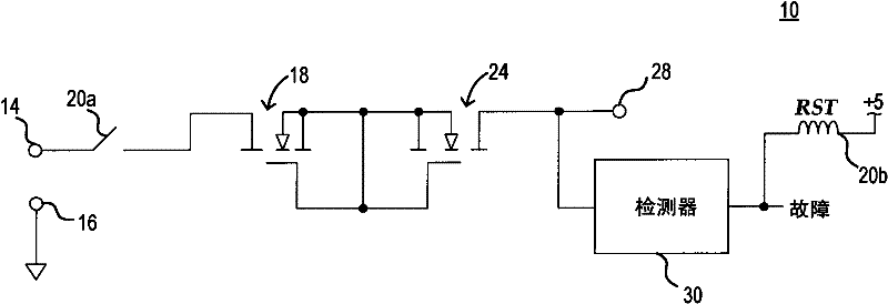
[0009] Figure 1 shows an embodiment of a prior art protection circuit 10 for an electronic device. The protection circuit 10 includes a pair of output terminals 14 , 16 , one of which is coupled to the drain of a first n-channel depletion mode field effect transistor (“FET”) 18 via a contact 20 a of a relay 20 . The coil that controls the conductive state of the contact 20a will be described below. The source of FET 18 is coupled to the source of second n-channel depletion FET 24 . The respective gates of FETs 18,24 are coupled to the sources of FETs 18,22. The drain of FET 24 is coupled both to terminal 28, which may be coupled to an output terminal of an electronic device (not shown), and to voltage detection circuit 30. The voltage detection circuit 30 detects a voltage greater than a certain voltage, and then applies a signal to the coil 20b of the relay 20, and then resets the relay to open the relay contact 20a. Thus, electronic devices coupled to terminal 28 are prot...


PUM


Abstract

A circuit for protecting an electronic device from excessive voltages applied to an input or output terminal includes a solid state relay coupling the electronic device to the terminal. The solid state relay may include an opto-transistor coupled between the electronic device and the terminal and a light emitting diode optically coupled to the opto-transistor. The solid state relay is coupled in series with a current limiting device, such as one or more enhancement mode field effect transistors. A voltage detector coupled to the terminal detects a voltage larger than a specific value and causes current to flow thorough the light emitting diode, thereby interrupting the coupling between the terminal and the electronic device. The voltage detector may be coupled between two spaced-apart connections to the coupling path between the terminal to the electronic device so that the voltage detector avoids diverting current from the coupling path.

Description

technical field [0001] Embodiments of the present invention relate to electronic devices having input terminals and / or output terminals, and in particular to methods for protecting said electronic devices from damage caused by excessive voltage applied to said input terminals and / or output terminals. Background technique [0002] Electronic devices generally have input terminals that receive various types of signals or output terminals that provide various types of output signals therefrom. In fact, many electronic devices have both such input terminals and output terminals. Such electronic devices include internal circuits or elements that are damaged when a voltage having a large magnitude is applied to an input terminal or an output terminal. For example, electronic test equipment will have output terminals from which precise output voltages or currents are provided. The magnitudes of these output voltages or currents are relatively low, and circuits or elements providi...

Claims


Application Information

Patent Timeline
Patent Type & Authority Applications(China)
IPC IPC(8): H02H3/20H02H9/02
CPCH03K17/0822H03K17/78
Inventor W·J·布里茨
Owner JOHN FLUKE MFG CO INC
Features
  • R&D
  • Intellectual Property
  • Life Sciences
  • Materials
  • Tech Scout
  • Unparalleled Data Quality
  • Higher Quality Content
  • 60% Fewer Hallucinations
Learn More