A mobile terminal shared antenna circuit

A technology for sharing antennas and mobile terminals. It is used in telephone communication, electrical components, and branch equipment. It can solve the problems of large overall size of mobile phones, difficult structure and shape design of mobile phones, and large space for antennas. And the effect of convenient shape design and overall size reduction

Inactive Publication Date: 2011-11-30
KONKA GROUP
View PDF0 Cites 22 Cited by
  • Summary
  • Abstract
  • Description
  • Claims
  • Application Information

AI Technical Summary

Problems solved by technology

Due to the large number of antennas, the antenna needs to occupy a large space, which brings difficulties to the structure and shape design of the mobile phone, making the overall size of the mobile phone large

Method used


Image

  • A mobile terminal shared antenna circuit
  • A mobile terminal shared antenna circuit
  • A mobile terminal shared antenna circuit

Examples


Embodiment Construction

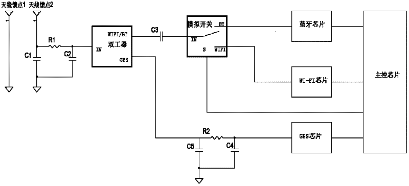
[0014] exist figure 1 In the shown embodiment 1 of the mobile terminal shared antenna circuit of the present invention, the mobile terminal shared antenna circuit includes an antenna, an antenna impedance matching circuit, a Bluetooth chip, a WI-FI chip, a GPS chip, a main control chip, and a duplexer (DGLT36M07 Manufacturer: EPCOS), single pole double throw switch (analog switch M508 manufacturer: HEXAWAVE) and GPS chip impedance matching circuit. The Bluetooth chip, WI-FI chip and GPS chip are respectively connected to the main control chip, and the antenna impedance matching circuit is a traditional structure, which is no different from the conventional design. The antenna impedance matching circuit is externally connected to the antenna through the antenna feed point, and the antenna impedance matching circuit is internally connected to the duplexer.

[0015] The Bluetooth / WI-FI signal output end of the duplexer is connected to the input end of the SPDT switch through the...


PUM


Abstract

The invention discloses a shared antenna circuit for a mobile terminal. An antenna impedance matching circuit of the shared antenna circuit is internally connected to a duplexer, and the Bluetooth / WI-FI signal output end of the duplexer is connected to the input end of a single-pole double-throw switch through a coupling capacitor. The GPS signal output terminal of the duplexer is connected to the GPS chip through the GPS chip impedance matching circuit; the control signal input terminal of the SPDT switch is connected to the control signal output terminal of the main control chip, and the Bluetooth signal output terminal of the SPDT switch is connected to the Bluetooth chip. The WI-FI signal output terminal of the SPDT switch is connected to the WI-FI chip. The invention enables GPS, WI-FI and Bluetooth to share one antenna, and the antenna needs to occupy a small space, which brings convenience to the structure and shape design of the mobile phone and reduces the overall size of the mobile phone.

Description

[technical field] [0001] The invention relates to a portable mobile terminal, in particular to a mobile terminal shared antenna circuit. [Background technique] [0002] There are many radio frequency systems in current mobile phones, such as mobile communication network (GSM), Bluetooth, WI-FI, GPS, FM, etc., all of which require the use of antennas. Therefore, in existing mobile phones, there are many antennas, and GPS, WI-FI, and Bluetooth all use independent antennas. Due to the large number of antennas, the antennas need to occupy a large space, which brings difficulties to the structure and shape design of the mobile phone, making the overall size of the mobile phone large. [Content of the invention] [0003] The technical problem to be solved by the present invention is to provide a mobile terminal sharing antenna circuit in which GPS, WI-FI and Bluetooth can share one antenna. [0004] In order to solve the above technical problems, the technical solution adopted ...

Claims


Application Information

Patent Timeline
Patent Type & Authority Applications(China)
IPC IPC(8): H04M1/725
Inventor 伍健
Owner KONKA GROUP
Why Eureka
Try Eureka