Arc head end mill

An end mill and arc head technology, applied in the field of arc head end mills, can solve the problems of blade strength change, damage to the roughness of the machined surface, load fluctuations, etc., to improve the roughness of the machined surface and prevent the end mill. effect of life

Active Publication Date: 2011-11-30
MITSUBISHI MATERIALS CORP
View PDF16 Cites 8 Cited by
  • Summary
  • Abstract
  • Description
  • Claims
  • Application Information

AI Technical Summary

Problems solved by technology

[0007] However, on the one hand, if a step portion or an intersecting ridge line intersecting the arc edge of the cutter head is formed on the rake face in this way, because the rake angle changes rapidly on both sides of the step portion or the intersecting ridge line, Therefore, the load applied during cutting also fluctuates and the strength of the blade also changes.
Therefore, especially in the arc-end end mill described in Patent Document 2, when the above-mentioned intersecting ridgelines intersect at the approximate center of the arc-radius edge of the cutter head, there is an effect on the side where the edge strength is weak or the cuttin

Method used


Image

  • Arc head end mill
  • Arc head end mill
  • Arc head end mill

Examples


Embodiment Construction

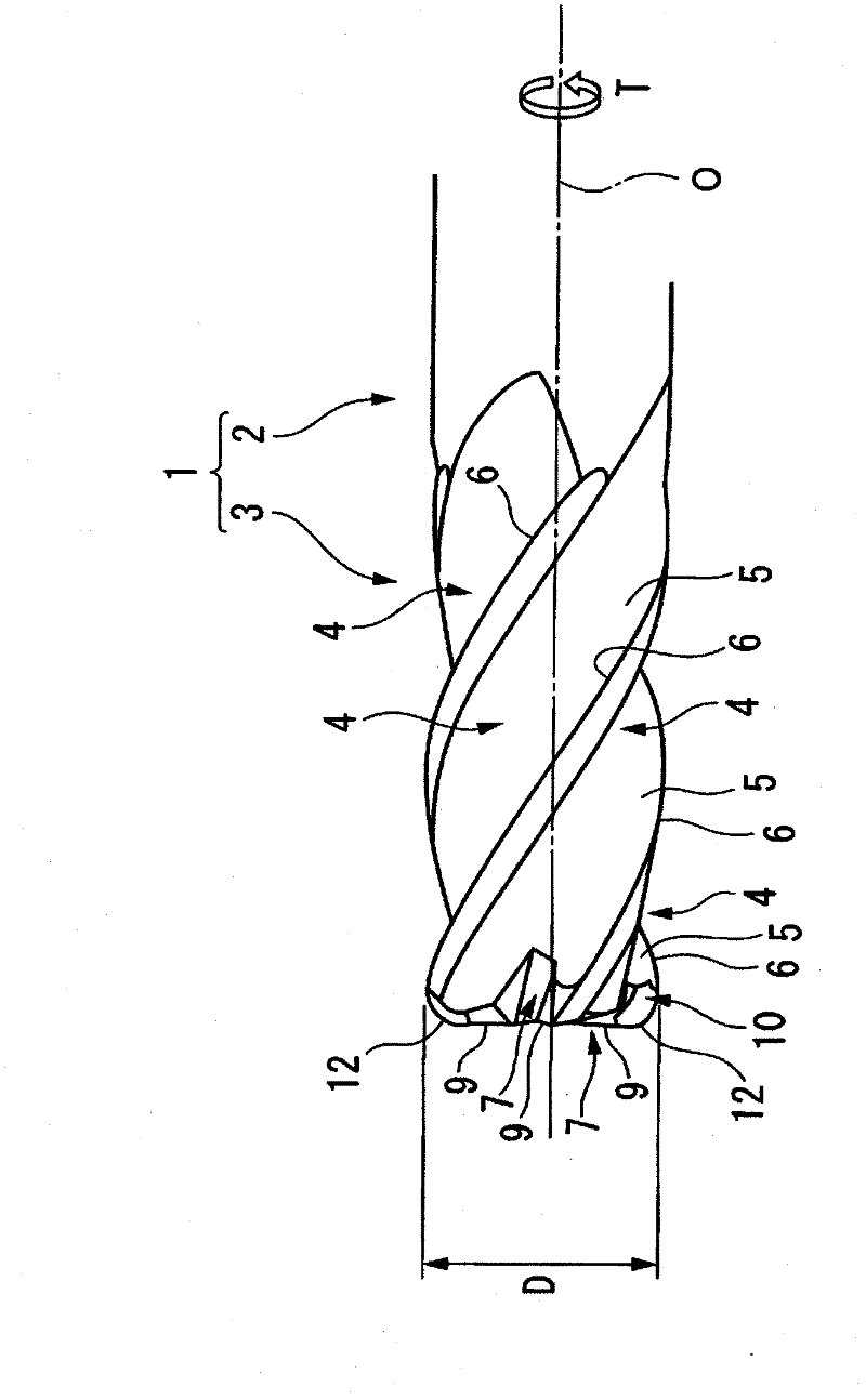
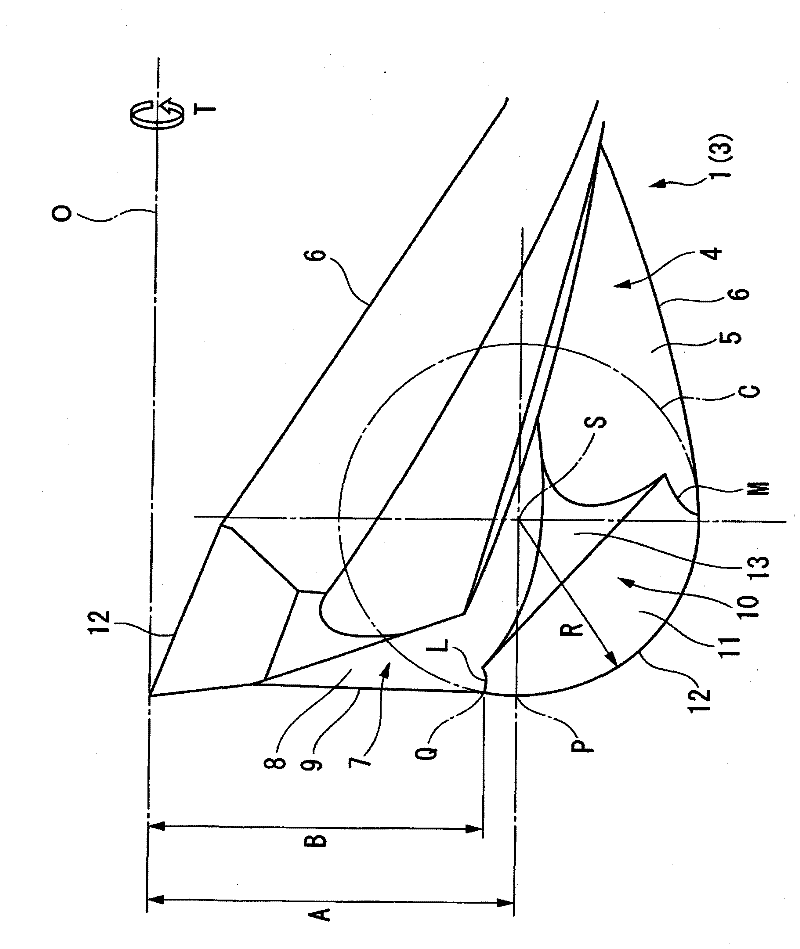
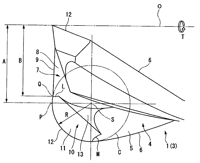
[0019] figure 1 and figure 2 It is a figure which shows one embodiment of the arc nose end mill of this invention. In this embodiment, the end mill main body 1 is integrally formed of a hard material such as cemented carbide into a substantially cylindrical shaft shape centered on the axis O, and its rear end side ( figure 1 and figure 2 The part on the right side in ) becomes the shank part 2 for installing the end mill body 1 on the spindle of the machine tool, and on the front end side ( figure 1 and figure 2 The middle left side) forms the cutting edge portion 3, and is sent out by the above-mentioned machine tool while rotating in the rotation direction of the end mill indicated by symbol T around the axis O, whereby the cutting process is performed on the workpiece by the cutting edge portion 3.

[0020] On the outer periphery of the blade portion 3, a plurality of (four in this embodiment) chip discharge grooves 4 are formed at equal intervals in the circumferent...


PUM


Abstract

Chipping of cutting edge due to weakened corner edge and roughened cut surface due to chipping can be prevented. At the lower end corner of a flute (4) at the outer periphery of an end mill body (1) which faces the direction of rotation (T) about an axis (O) is provided a rake face (11) with a corner edge (12) at its outer edge capable of forming a convex shape when rotated about the axis (O). Radially inside of the rake face (11) is provided a gash (7) having a bottom rake face (8) which faces the direction of rotation (T). The bottom rake face has a bottom edge (9) at the end of the end mill extending radially inwardly from the corner edge (12). The line (L) of intersection between the rake face (11) and the rake face (8) ends at the point (Q) which locates radially inside of the center (S) of the corner edge (12) and axially rearward of the lowest point (P) of the corner edge (12).

Description

technical field [0001] The present invention relates to a circular arc head end mill in which a convex arc-shaped cutting edge is formed on the outer periphery of the front end of the end mill main body. Background technique [0002] As such a circular arc nose end mill, for example, Patent Document 1 proposes a circular arc nose end mill formed by forming a main cut surface on the inner peripheral side of the front end portion of the wall surface of the chip discharge flute facing the tool rotation direction, and The bottom edge is formed at the front end of the main notch surface, and the sub-notch surface is formed on the outer peripheral side of the main notch surface in such a way that the step portion retreats relative to the main notch surface, and a substantially convex arc is formed from the front end of the sub-notch surface to the outer periphery. The circular arc edge of the cutter head is connected with the outer peripheral side of the bottom edge. [0003] In ...

Claims


Application Information

Patent Timeline
IPC IPC(8): B23C5/10
CPCB23C2210/084B23C5/10B23C5/02Y10T407/1948Y10T407/1964
Inventor 高木优次北浦精一郎
Owner MITSUBISHI MATERIALS CORP
Why Eureka
Try Eureka