Exhaust purification device for internal combustion engines

An exhaust gas purification device, a technology for an internal combustion engine, which is applied in the direction of an exhaust device, an internal combustion piston engine, a muffler device, etc., can solve the problems such as the deterioration of the fuel efficiency of the internal combustion engine.

Inactive Publication Date: 2011-11-30
TOYOTA JIDOSHA KK
View PDF7 Cites 2 Cited by
  • Summary
  • Abstract
  • Description
  • Claims
  • Application Information

AI Technical Summary

Problems solved by technology

For this reason, there is a problem that the fuel efficiency of the internal combustion engine deteriorates

Method used


Image

  • Exhaust purification device for internal combustion engines
  • Exhaust purification device for internal combustion engines
  • Exhaust purification device for internal combustion engines

Examples


Embodiment approach 1

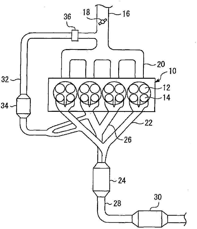
[0042] figure 1 It is a figure which shows the internal combustion engine in Embodiment 1 of this invention. figure 1 The illustrated internal combustion engine 10 is used as a power source of a vehicle or the like. The internal combustion engine 10 of the present embodiment is a spark ignition type internal combustion engine provided with a fuel injector (not shown) that directly injects fuel into a cylinder. This internal combustion engine 10 is of a series 4-cylinder type. However, in the present invention, the number of cylinders and the arrangement of cylinders are not particularly limited. Two intake valves 12 and two exhaust valves 14 are provided in each cylinder.

[0043] An intake pipe 16 is connected to the internal combustion engine 10 . On the way of the intake pipe 16, a throttle valve 18 for controlling the amount of intake air is provided. Intake gas supplied from the intake pipe 16 is distributed by the intake manifold 20 and flows into the cylinders.

...

Embodiment approach 2

[0075] Next, refer to Image 6 , Embodiment 2 of the present invention will be described, but the description will focus on the points of difference from Embodiment 1 described above, and descriptions of the same items will be simplified or omitted. Using the same hardware configuration as the above-mentioned Embodiment 1, instead of Figure 4 Shown program, make ECU50 carry out the following Image 6 The program shown in this example implements this embodiment.

[0076] In the first embodiment described above, whether or not the amount of PM flowing into the catalyst is greater than the second threshold β is determined based on the presence or absence of acceleration, but in this embodiment, the number of PM particles in the engine exhaust gas is directly compared with the second threshold β.

[0077] Image 6 It is a flowchart of a program executed by ECU 50 in the present embodiment to realize the above-mentioned functions. according to Image 6 The shown routine first...

Embodiment approach 3

[0084] Next, refer to Figure 7 , Embodiment 3 of the present invention will be described, but the description will focus on the points of difference from Embodiments 1 and 2 described above, and descriptions of the same items will be simplified or omitted.

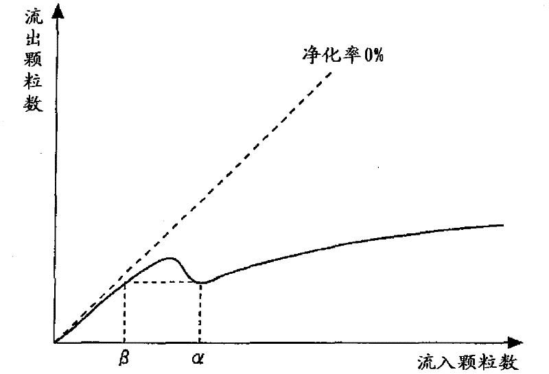
[0085] As mentioned above, the catalytic converter that combusts PM is expressed as image 3 characteristics as shown. That is, in the graph showing the relationship between the amount of PM flowing into the catalyst and the amount of PM flowing out of the catalyst, there is a portion where the amount of PM flowing out of the catalyst decreases as the amount of PM flowing into the catalyst increases.

[0086] However, according to the findings of the inventors of the present invention, in the region where the space velocity SV of the catalytic converter is somewhat large, the image 3 characteristics as shown. That is, in a region where the space velocity SV of the catalytic converter is to a certain extent, the charac...


PUM


Abstract

The present invention relates to an exhaust gas purifying apparatus for an internal combustion engine. An object of the invention is to reduce the amount of particulate matter that flows out from a catalytic converter that continuously burns particulate matter contained in an exhaust gas. The exhaust gas purifying apparatus for an internal combustion engine of the present invention includes a catalytic converter that continuously burns particulate matter contained in an exhaust gas; particle amount acquisition means that acquires an inflow amount of particulate matter to the catalytic converter; and particle amount increase means that, when an acquired inflow amount of particulate matter is less than a predetermined threshold value ±, changes a value of a control parameter of the internal combustion engine in a direction such that the inflow amount of particulate matter to the catalytic converter increases. The threshold value ± corresponds to a value of a particulate matter inflow amount to the catalytic converter at a time when a particulate matter outflow amount from the catalytic converter is a local minimum in a graph showing a relation between a particulate matter inflow amount to the catalytic converter and a particulate matter outflow amount from the catalytic converter.

Description

technical field [0001] The present invention relates to an exhaust purification device for an internal combustion engine. Background technique [0002] The exhaust gas of an internal combustion engine contains particulate matter (Particulate Matter), which is a fine particle mainly composed of carbon. Conventionally, exhaust gas purification devices that provide filters in exhaust passages and capture particulate matter with the filters have been widely used. As particulate matter accumulates in the filter, the pressure loss (ventilation resistance) of the filter increases. For this reason, an exhaust gas purification device including such a filter needs to regularly perform regeneration control for burning and removing particulate matter accumulated in the filter. [0003] Generally, a temperature of 550° C. or higher is required to burn the particulate matter accumulated in the filter. Japanese Patent Laid-Open No. 2005-90390 discloses the following technology: For a di...

Claims


Application Information

Patent Timeline
Patent Type & Authority Applications(China)
IPC IPC(8): F01N3/02
CPCB01D2255/2066F01N13/02B01D2255/2065F02D41/0235F02M25/074Y02T10/44F02M25/0749B01D53/944B01D53/9477F02D41/401B01D2255/2068F02M25/0718F02D41/1467F01N13/107F01N3/103F01N3/0231F02M25/07F01N13/009F02M26/15F02M26/35F02M26/43Y02T10/40
Inventor 樱井健治宫下茂树
Owner TOYOTA JIDOSHA KK
Why Eureka
Try Eureka