Devices for handling liquids

A liquid and liquid pipeline technology, applied in the field of liquid processing devices, can solve problems such as unit integrated circulation systems that do not know condensation diagnosis, and achieve the effect of low cost

Active Publication Date: 2015-12-09
ROBERT BOSCH GMBH
View PDF4 Cites 0 Cited by
  • Summary
  • Abstract
  • Description
  • Claims
  • Application Information

AI Technical Summary

Problems solved by technology

[0011] Integration of the coagulation diagnostic unit into the extracorporeal circulatory system is currently unknown

Method used


Image

  • Devices for handling liquids
  • Devices for handling liquids
  • Devices for handling liquids

Examples


Embodiment Construction

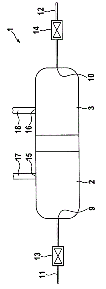
[0037] figure 1 A device 1 according to the invention for treating liquids is shown. The device 1 is suitable, for example, to improve the mixing effect of two liquids or also to accelerate the dissolution process. In addition, the device according to the invention is used for testing liquids.

[0038] In particular, the device 1 is a microfluidic device, but is not restricted to the scope of microfluidics. Rather, the device 1 according to the invention can also be produced and used as a macrofluidic device. By microfluidic device is meant here a device in at least one dimension in the submillimeter range.

[0039] The device 1 according to the invention comprises two interior chambers, namely a first interior chamber 2 and a second interior chamber 3 . The inner chambers 2, 3 preferably consist of a polymer material. For example, the interior consists of a polymer metallized, for example by metal spraying with copper, nickel, gold or mixtures of these metals. The two i...


PUM


Abstract

The device (1) has two chambers (2, 3) comprising liquid regions (4, 5) that are separated from fluid regions (7, 8) through a flexible material (6) i.e. thermoplastic elastomer. The liquid regions of the chambers are connected to each other. The liquid regions include liquid connectors (9, 10) that are connected with liquid lines (11, 12), and fluid connectors that are connected with fluid lines. Valves (13, 14) are arranged in the liquid lines or on the liquid connectors for fluid-tightly sealing the liquid lines. Mixer elements are arranged on the liquid regions.

Description

technical field [0001] The invention relates to a device for treating liquids. In particular, the invention relates to a device for mixing liquids and / or for dissolving solids in liquids and / or for testing liquids. Background technique [0002] Especially in microfluidic systems, the mixing of two fluids or the dissolution of solids in a fluid becomes a problem. In microfluidic systems, it is often quite difficult to integrate convective elements or to realize convective effects. The main transport mechanism at such a small scale is rather diffusion, which in the case of larger molecules can be quite slow, and in some instances significantly greater than 14 hours per centimeter or even a day. If, for example, a solid is to be dissolved in a fluid in a microcavity, this process may take several hours until a homogeneous distribution of the solid is achieved in the solution. It also lasts longer until the molten material diffuses again when it separates, for example at the ...

Claims


Application Information

Patent Timeline
Patent Type & Authority Patents(China)
IPC IPC(8): B01F13/00B01F3/08B01F1/00
CPCB01F5/061B01F11/0065B01F13/0059B01F15/00207B01F15/00246B01F2005/0636G01N11/02G01N33/4905G01N2011/0066B01F25/431B01F25/431971B01F31/55B01F33/30B01F35/213B01F35/2136B01F25/4317
Inventor P.罗特歇尔
Owner ROBERT BOSCH GMBH
Why Eureka
Try Eureka