Active clamping mechanism for hole forming of non-magnetic member

A clamping mechanism, non-magnetic technology, applied in the direction of clamping, manufacturing tools, metal processing machine parts, etc., can solve the problems of low clamping and positioning accuracy, cumbersome operation of the component hole-making clamping mechanism, etc., to achieve convenient adjustment, structural Simple, accurate hole-making results

Inactive Publication Date: 2011-12-07
NANJING UNIV OF AERONAUTICS & ASTRONAUTICS
View PDF4 Cites 1 Cited by
  • Summary
  • Abstract
  • Description
  • Claims
  • Application Information

AI Technical Summary

Problems solved by technology

[0003] In order to solve the problems of cumbersome operation and low clamping and positioning accuracy of the existing component hole-making and clamping mechanism, the present inventi...

Method used


Image

  • Active clamping mechanism for hole forming of non-magnetic member
  • Active clamping mechanism for hole forming of non-magnetic member
  • Active clamping mechanism for hole forming of non-magnetic member

Examples


Embodiment Construction

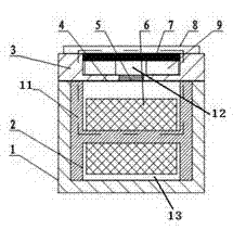
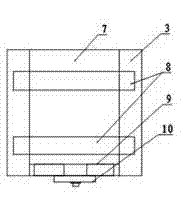
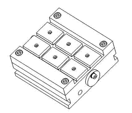
[0012] The implementation of the active clamping mechanism for making holes in the non-magnetic connecting member of the present invention will be described below with reference to the accompanying drawings. As shown in Figure 1, the mechanism mainly includes a base 1, an H-shaped magnetic core 2, a panel pole 3, a horizontal panel 4, a magnet spacer 5, a coil 6, an iron bead 8, a group of pads 9, and a positioning block 10. The H-shaped magnetic core 2 is installed in the base body 1; the coil 6 is wound at the middle groove of the H-shaped magnetic core 2, and the magnetic induction line is generated through the upper half of the magnetic core, the magnetic pole 3 and the iron bead 8 to form a magnetic circuit. ; The end cover and the base body 1 are fastened with connecting screws; the group of pads 9 are fastened on the end cover with connecting screws; Play the role of clamping workpiece 7. Such as figure 2 As shown, the positioning block is connected to the base body ...


PUM


Abstract

The invention provides an active clamping mechanism for hole forming of a non-magnetic member and belongs to the technical field of the active clamping mechanism. The active clamping mechanism mainly comprises a base body, an H-shaped magnetic core, coils, a horizontal panel, a group cushion block, a positioning stop block and an iron pressing strip. By adopting a novel winding mode, a non-magnetic connecting member can be quickly clamped, positioned and disassembled; and by adoption of the group cushion block, the active clamping mechanism can be quickly adjusted and can protect a tool and aclamp from being damaged in the process of hole forming operation. The active clamping mechanism is simple and compact in structure and convenient to adjust and disassemble, and can meet requirementsfor accurate hole forming and high-efficiency clamping of the non-magnetic connecting member during the assembly of an airplane.

Description

technical field [0001] The invention relates to a clamping mechanism, in particular to an active clamping mechanism for forming a hole in a non-magnetic connecting member. Background technique [0002] At present, mechanical clamping is widely used in the hole making and clamping of aircraft non-magnetic components, using screws, clamps, C-shaped clamps, etc. to clamp. Due to the cumbersome operation and poor openness of the traditional clamping method, there is a large clamping deformation, which has a great impact on the accuracy and quality of the hole making; in addition, the ordinary mechanical clamping operation is complicated and the hole making efficiency is low, so the traditional Clamping is not suitable for hole making for modern automated assembly. The active clamping mechanism based on the electromagnetic sucker adopted by the present invention has the advantages of easy use, fast disassembly of the workpiece, saving man-hours, and safety and reliability....

Claims


Application Information

Patent Timeline
IPC IPC(8): B23Q3/00
Inventor 韦红余陈文亮
Owner NANJING UNIV OF AERONAUTICS & ASTRONAUTICS
Why Eureka
Try Eureka