Optical lens for camera

An optical lens and lens technology, applied in optics, optical components, instruments, etc., can solve problems such as difficulty in aberration correction, affecting imaging quality, etc., to achieve the effect of reducing sensitivity, good imaging quality, and reducing the total length of the lens

Active Publication Date: 2011-12-07
LARGAN PRECISION
View PDF7 Cites 8 Cited by
  • Summary
  • Abstract
  • Description
  • Claims
  • Application Information

AI Technical Summary

Problems solved by technology

U.S. Patent No. 7,564,635 discloses a camera lens with three lenses, but the three lenses are all positive refractive lens

Method used


Image

  • Optical lens for camera
  • Optical lens for camera
  • Optical lens for camera

Examples


no. 1 example 》

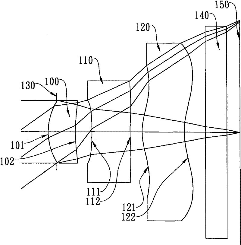
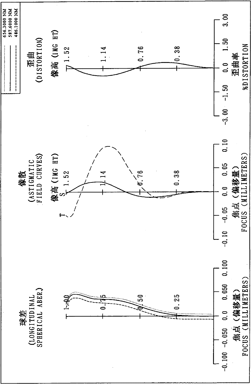
[0099] Please refer to the schematic diagram of the optical system of the first embodiment of the present invention Figure 1A , please refer to the aberration curve of the first embodiment Figure 1B . The optical lens for imaging in the first embodiment is mainly composed of three lenses, which sequentially include from the object side to the image side:

[0100] A first lens 100 with positive refractive power, its object-side surface 101 is convex and image-side surface 102 is concave, its material is plastic, the object-side surface 101 and image-side surface 102 of the first lens 100 are both aspherical ;

[0101] A second lens 110 with negative refractive power, its object-side surface 111 and image-side surface 112 are both concave surfaces, and its material is plastic, and the object-side surface 111 and image-side surface 112 of the second lens 110 are both aspherical, And the image side surface 112 of the second lens 110 is provided with two inflection points; and ...

no. 2 example 》

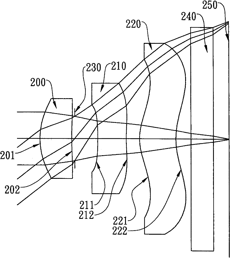
[0129] Please refer to the schematic diagram of the optical system of the second embodiment of the present invention Figure 2A , for the aberration curve of the second embodiment, please refer to Figure 2B . The optical lens for imaging in the second embodiment is mainly composed of three lenses, which sequentially include from the object side to the image side:

[0130] A first lens 200 with positive refractive power, its object-side surface 201 is convex and image-side surface 202 is concave, its material is plastic, the object-side surface 201 and image-side surface 202 of the first lens 200 are both aspherical ;

[0131] A second lens 210 with negative refractive power, its object-side surface 211 and image-side surface 212 are both concave, and its material is plastic, and the object-side surface 211 and image-side surface 212 of the second lens 210 are both aspherical, And the image side surface 212 of the second lens 210 is provided with an inflection point; and

...

no. 3 example 》

[0153] Please refer to the schematic diagram of the optical system of the third embodiment of the present invention Figure 3A , for the aberration curve of the third embodiment, please refer to Figure 3B . The optical lens for imaging in the third embodiment is mainly composed of three lenses, which sequentially include from the object side to the image side:

[0154] A first lens 300 with positive refractive power, its object-side surface 301 is convex and image-side surface 302 is concave, its material is plastic, the object-side surface 301 and image-side surface 302 of the first lens 300 are both aspherical ;

[0155] A second lens 310 with negative refractive power, its object-side surface 311 and image-side surface 312 are concave, its material is plastic, the object-side surface 311 and image-side surface 312 of the second lens 310 are both aspherical, And the image side surface 312 of the second lens 310 is provided with two inflection points; and

[0156] A thir...


PUM


Abstract

The invention discloses an optical lens for shooting, which comprises a first lens with positive refractive power, a second lens with negative refractive power and a third lens from an object side to an image side in turn, wherein an object side surface of the first lens is a convex surface; an object side surface of the second lens is a concave surface, and an image side surface of the second lens is a concave surface; the object side surface and the image side surface of the second lens are aspheric surfaces; an image side surface of the third lens is a concave surface; an object side surface and the image side surface of the third lens are aspheric surfaces; and at least one inflection point is arranged on the image side surface of the third lens. Three lenses with refractive power arearranged in the optical lens for shooting. Due to the configuration mode of the lens, the total length of the lens can be effectively shortened, the sensitivity of an optical system is reduced, and high imaging quality is achieved.

Description

technical field [0001] The invention relates to an optical lens for imaging, in particular to a miniaturized optical lens for imaging that is applied to portable electronic products. Background technique [0002] In recent years, with the rise of portable electronic products with camera functions, the demand for miniaturized camera lenses has increased day by day, and the photosensitive element of general camera lenses is nothing more than a charge coupled device (CCD) or complementary There are two types of Complementary Metal-Oxide Semiconductor Sensor (CMOS Sensor), and with the improvement of process technology, the pixel size of the photosensitive element is reduced, and the miniaturized camera lens is gradually developing into the high-pixel field. Therefore, the imaging quality requirements are also increasing. [0003] Commonly seen miniaturized camera lenses, in order to reduce manufacturing costs, mostly adopt a two-piece lens structure, such as U.S. Patent No. 7,...

Claims


Application Information

Patent Timeline
IPC IPC(8): G02B13/00G02B13/18G02B13/22
Inventor 谢东益陈俊杉蔡宗翰
Owner LARGAN PRECISION
Why Eureka
Try Eureka