A virtual desktop external device support system

A technology for external equipment and support systems, applied in the direction of transmission systems, electrical components, instruments, etc., can solve problems such as different, poor support of peripheral equipment, and difficulty in achieving a high degree of interoperability equipment sharing system

Inactive Publication Date: 2011-12-07
HUAZHONG UNIV OF SCI & TECH
View PDF3 Cites 36 Cited by
  • Summary
  • Abstract
  • Description
  • Claims
  • Application Information

AI Technical Summary

Problems solved by technology

[0003] Currently, the conventional device sharing model does not support emerging peripherals very well
First, only application-level operations are shared, so finer-grained and device-specific operations are not supported, which makes it impossible to use shared remote devices like directly connected devices
Second, in terms of original function, the remote device and the locally connected device are the same, however, the interfaces used to control the two devices are often different
But a VNC client is running a user-mode application, which does not provide the same access interface as the local physical framebuffer
Third, sometimes achieving a high degree of interoperability is difficult for a device-sharing system due to the complexity of sharing device operating systems
Some shared device applications (such as simply forwarding device requests by extending an existing abstraction layer) usually only support the same operating system and cannot interoperate with operating systems that do not have such an abstraction layer
In addition, the interoperability problem often conflicts with the first problem above. To bridge the conflict between different operating system abstraction layers, it is usually necessary to disable some specific functions of the shared device.

Method used


Image

  • A virtual desktop external device support system
  • A virtual desktop external device support system
  • A virtual desktop external device support system

Examples


Embodiment Construction

[0015] The method of the present invention will be further described in detail below with reference to the accompanying drawings and taking the USB external device as an example.

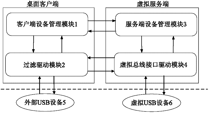
[0016] Such as figure 1 As shown, the system of the present invention includes a filter driver module 2 and a client device management module 1 located at the desktop client, and a server device management module 3 and a virtual bus interface driver module 4 located at the virtual server.

[0017] The client device management module 1 is used to share the USB device of the desktop client and provide it to the virtual server to use, and to uninstall the USB device from the driver module of the operating system, that is, to write the USB device interface number into the unbinding under the original driver. file, and then bound to the filter driver module 2 of the system to complete the binding of the USB device and perform real-time monitoring of the state conversion of the USB device, and at the same...


PUM


Abstract

The invention discloses a virtual desktop external equipment support system, comprising a filter driving module, a client equipment management module, a server equipment management module and a virtual bus interface driving module. The virtual external bus interface driving module is used for setting up virtual equipment in a virtual environment according to shared real equipment, packaging a command of operating the virtual equipment into a network request packet, and forwarding the network request packet to the desktop client through a transmission interface. The filter driving module is used for receiving data forwarded by the virtual external bus interface driving module, resolving a command, and controlling physical equipment of a computer according to the command. The client equipment management module and the server equipment management module are used for establishing a connection between a desktop client and a virtual server, coordinating the data transmission and receiving between virtual equipment and real equipment, and providing a channel for data communication between the user mode and the kernel. According to the invention, the difference between the virtual equipment of the virtual desktop and the interface of the local physical equipment is completely hidden in a host control drive layer.

Description

technical field [0001] The invention relates to the technical field of virtual desktop external device support, more specifically, provides a system for accessing desktop client external devices under the virtual desktop platform. Background technique [0002] The current virtual desktop platform is sought after by people, and corresponding virtual desktop solutions have emerged as the times require. For example, virtual desktop technology solves the problems of remote virtual display of applications, rapid construction of the user's local environment, migration of the user environment, and so on. And the external equipment of the computer has the characteristics of high speed, easy to carry, easy to use and supports plug and play, so it has been widely used in the computer field. For example, products such as USB chargers, USB mobile CD-ROM drives, USB network cards, and USB audio devices that are currently on the market are welcomed by the majority of computer users. Howe...

Claims


Application Information

Patent Timeline
Patent Type & Authority Applications(China)
IPC IPC(8): G06F13/10H04L29/06
Inventor 廖小飞金海谢晓周晔
Owner HUAZHONG UNIV OF SCI & TECH
Why Eureka
Try Eureka