
Charging control circuit and charging method thereof

A charging control and circuit technology, applied in the field of charging control circuit, can solve the problems of long charging time, low voltage, useless exposure and filling time, etc., and achieve the effect of shortening the charging time

Active Publication Date: 2014-02-19
CRM ICBG (WUXI) CO LTD
View PDF4 Cites 0 Cited by
  • Summary
  • Abstract
  • Description
  • Claims
  • Application Information

AI Technical Summary

Problems solved by technology

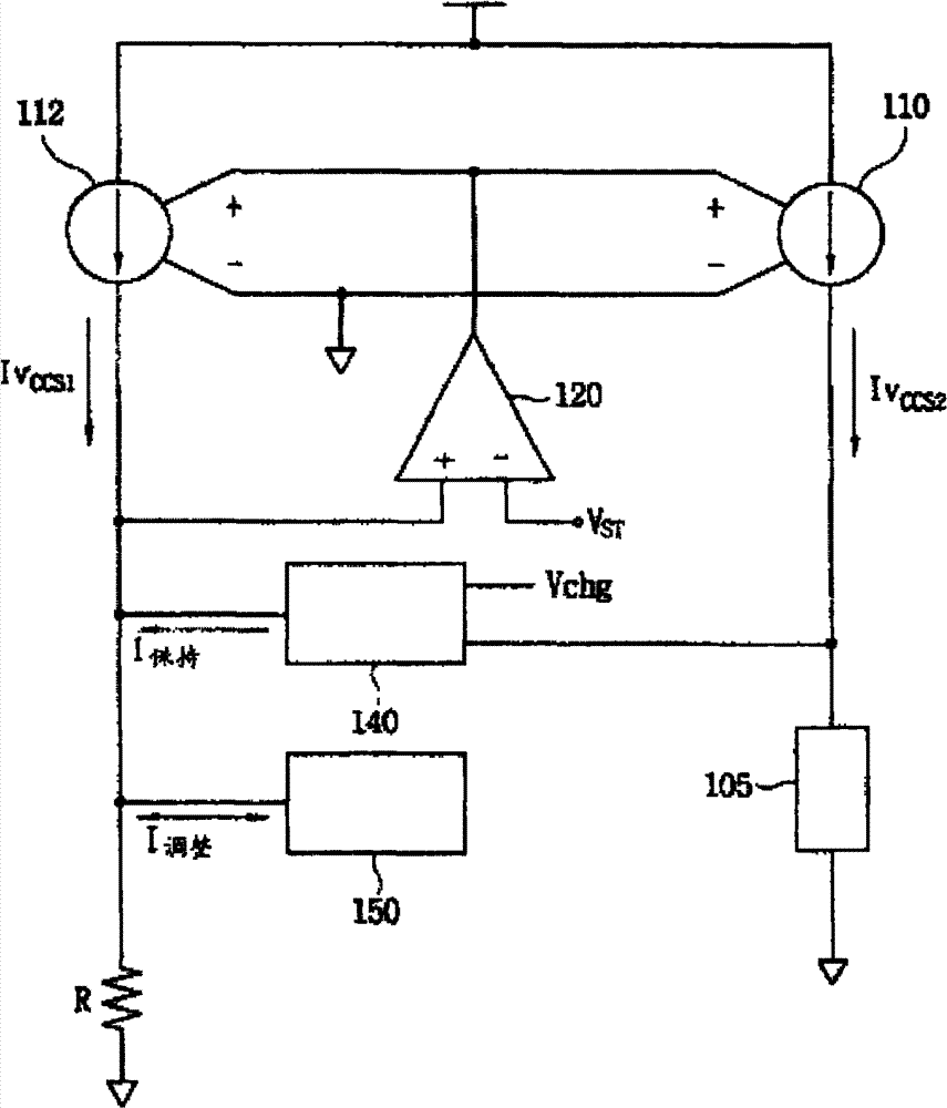
However, due to the contact resistance between the battery and the charger during charging, the series resistance caused by the wires from the output end of the circuit to the battery, and the internal resistance of the battery itself during charging, etc., the additional resistance caused by the cumulative charging circuit resistance of these factors The voltage drop causes the stop charging voltage to deviate from the true value, that is, there is a defect that the actual measured voltage at both ends of the battery is smaller than Vchg
And this published patent also fails to disclose how to stop the filling time of charging the battery, which may lead to the defect that the charging time is too long

Method used


Image

  • Charging control circuit and charging method thereof
  • Charging control circuit and charging method thereof
  • Charging control circuit and charging method thereof

Examples


Embodiment Construction

[0018] Aiming at the defects that the traditional charging circuit takes too long to charge the battery and the actual charged voltage is too small, the present invention provides a charging control circuit.

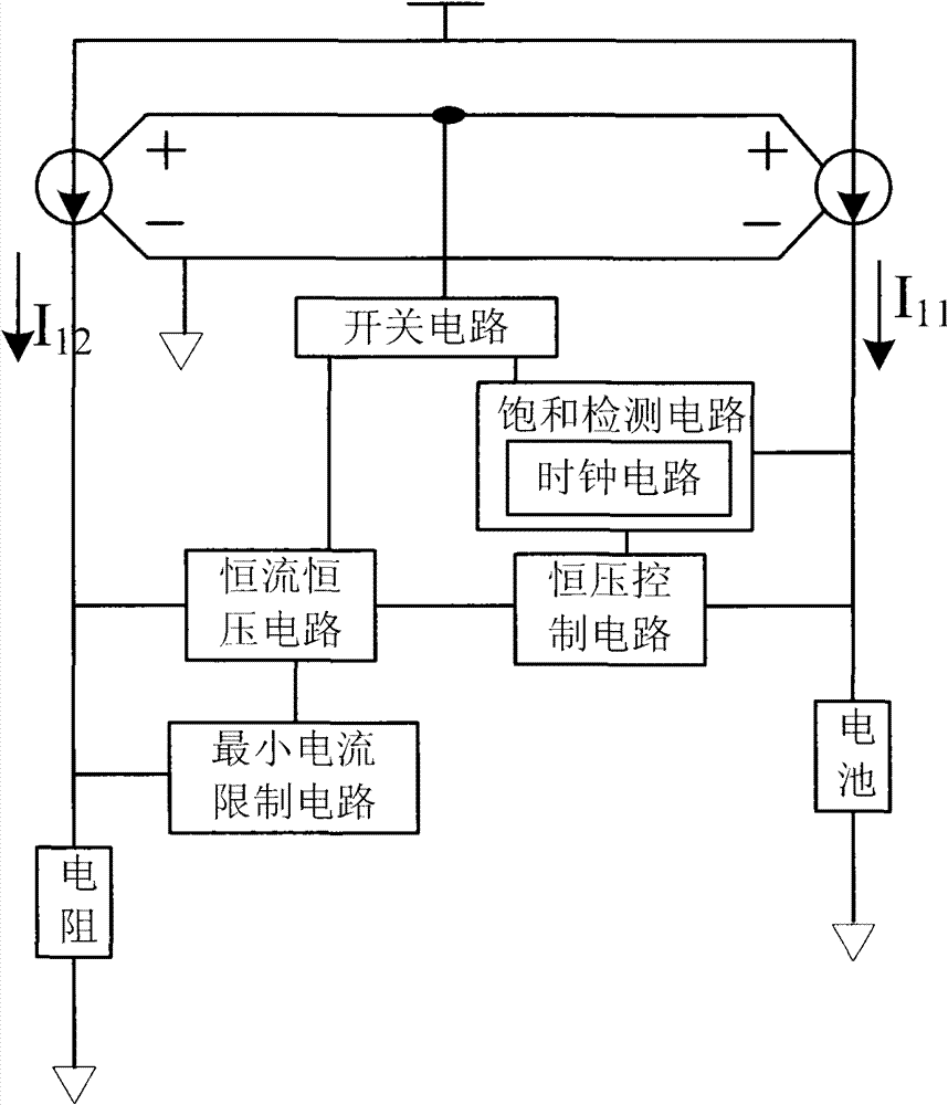
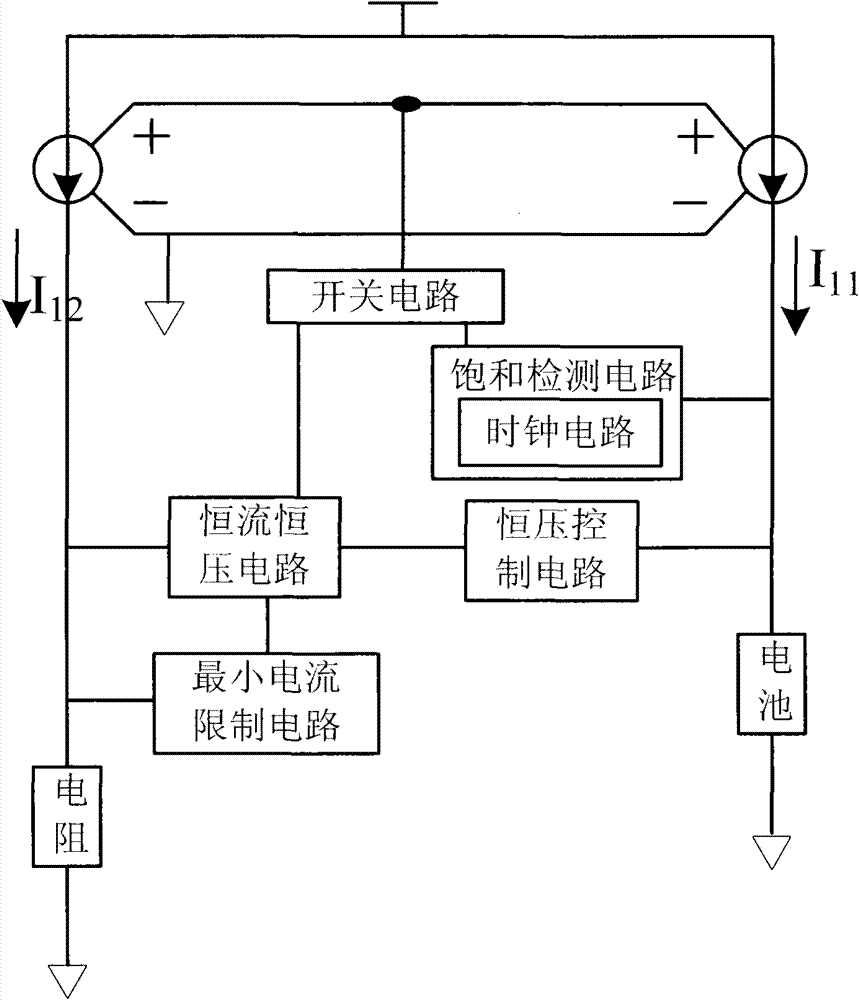
[0019] figure 2 A charging control circuit according to one embodiment of the present invention is described. The charging control circuit has a voltage-controlled current source that generates currents I11 and I12 in response to the applied voltage, and the voltage-controlled current sources respond to the same voltage applied to each body to generate substantially equal currents I11 and I12, that is, the voltage-controlled current source can be based on the The applied voltage acts as a mirror current source producing equal currents.

[0020] Such as figure 2 As shown, the charging control circuit mainly includes a switch circuit, a constant current and constant voltage circuit, a constant voltage control circuit, a minimum current limiting circuit and a saturation...


PUM


Abstract

The invention discloses a charging control circuit and a charging method thereof. The charging control circuit mainly comprises a constant-current constant-voltage circuit, a constant-voltage control circuit, a saturation detection circuit and a minimum current limit circuit, wherein the constant-current constant-voltage circuit is used for charging a battery in a constant voltage mode firstly by utilizing the output of the constant-current constant-voltage circuit, and then charging the battery by utilizing the output in a constant current mode converted under the control of the constant-voltage control circuit; and when the battery is approximately fully charged, the minimum current limit circuit is used for limiting the constant-current and constant-voltage circuit to output the minimum voltage to charge the battery in a minimum current charging mode. According to the charging control circuit disclosed by the invention, the minimum current limiting circuit is used for controlling the minimum charging current of the charging control circuit, and the effect of reducing the charging time is achieved.

Description

technical field [0001] The invention relates to the technical field of batteries, in particular to a charging control circuit and a charging method thereof. Background technique [0002] For some types of batteries such as lithium batteries, when the battery voltage is low, that is, when the battery is low, the battery has a large capacity and can be charged with a larger current. When the battery power is close to full capacity, the ability of the battery to absorb current will be small. If you continue to apply high current charging, there will be problems, which may cause battery damage. Therefore, when the battery capacity is close to full capacity, the constant voltage mode is generally used to charge the battery. Therefore, the charging method of constant current and constant voltage is recognized by the industry. [0003] The so-called constant current and constant voltage charging method means that a constant current is first applied to charge the battery, and then ...

Claims


Application Information

Patent Timeline
Patent Type & Authority Patents(China)
IPC IPC(8): H02J7/00
Inventor 刘卫中牛瑞萍孔祥艺刘君
Owner CRM ICBG (WUXI) CO LTD
Learn More