Transportation systems that charge vehicles while they are in motion

A traffic system and vehicle driving technology, applied in electric vehicle charging technology, charging stations, vehicle energy storage, etc., can solve problems such as rising battery prices, reduce emissions, and eliminate charging waiting time

Inactive Publication Date: 2011-12-07
北口弘正
View PDF1 Cites 7 Cited by
  • Summary
  • Abstract
  • Description
  • Claims
  • Application Information

AI Technical Summary

Problems solved by technology

[0005] In the past, many companies extended the driving distance of vehicles by improving the performance of expensive batteries installed in battery vehicles. However

Method used


Image

  • Transportation systems that charge vehicles while they are in motion
  • Transportation systems that charge vehicles while they are in motion
  • Transportation systems that charge vehicles while they are in motion

Examples


Embodiment Construction

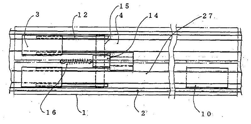
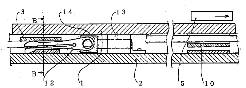
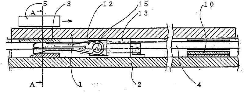
[0079] right Figure 1 to Figure 9 structure is described.

[0080] Among them, 1 is the top rail; 2 is the frame rail; 3 is the conductive plate; 4 is the wire A; 5 is the magnet; 6 is the wheel, which moves up and down together with the magnet 5; 7 is the ground plate; 8 is the ground wire; 9 is an insulating plate; 10 is a disconnecting plate; 11 is a terminal; 12 is a holding plate, which is formed by an insulating material; 13 is an electromagnetic coil; 14 is a pin; 15 is a mounting rod for the holding plate, which is formed by an insulating material; 16 is a spring; 17 is the driver up and down for the wheel. 18 is an insulating separation belt, which separates the two poles of electricity; 19 is a main switch under the situation of electric mode; 20 is a control element that also includes a timer. 21 is a proximity sensor A, and 22 is a proximity sensor B, which transmits signals to the control element 20 through magnetic induction. 23 is a vehicle.

[0081] Below,...


PUM


Abstract

Provide an electric vehicle transportation system that reduces CO 2 emissions and also enables automatic driving to prevent accidents caused by the driver dozing off or losing attention, in light of the situation of late where reduction of CO 2 emissions has become critical to one of the greatest problems causing environmental destruction and where vehicles that use gasoline, diesel oil and other fossil fuels are among the various things that generate a lot of CO 2 . This vehicle transportation system promotes a widespread use of storage-cell-powered vehicles by minimizing the number of storage cells installed on them and thereby reducing their cost. The system involves laying rails that carry current on roads, where only the rails that are passed by vehicles carry current. In addition, the system releases earth leakage current by means of grounding to ensure safety even during rain, so that even storage-cell-powered vehicles can drive long distances by recharging themselves while traveling. Since this is a single-rail system, driving a vehicle becomes much easier and there is also peace of mind because the vehicle can be driven by using the electricity received from the rail to drive the motor, turn on the lights at night, and heat the cabin in winter or cool it in summer, without worrying about electricity running short. At the same time the storage cells are constantly charged to allow for continuous driving as long as there is a rail, and thereby reducing CO 2 generated from such continuous driving.

Description

technical field [0001] The present invention relates to a traffic system with rails of simple structure, according to which switches and the like are provided in the rails for transmitting electricity, and electric wires and the like are laid between the rails. [0002] According to the transportation system of the present invention, by popularizing the above-mentioned rails of the present invention and carrying them as little as possible, it is possible to effectively reduce CO 2 Discharged batteries are used to reduce the price of vehicles to increase the penetration rate of electric vehicles, and rails that can be used to collect electricity are laid on the roads to provide driving power for vehicles and charge batteries, which is expected to reduce CO2. 2 emissions. [0003] In addition, in the transportation system of the present invention, Hall elements or proximity sensors are arranged in the rails. When a vehicle approaches or passes by, the Hall elements or proximity...

Claims


Application Information

Patent Timeline
IPC IPC(8): B60M7/00B60L5/38B60L11/18B60M1/10H02J7/00
CPCY02T90/14Y02T90/121B60M1/106Y02T10/646B60L2200/26Y02T10/648Y02T10/7088B60L11/1816Y02T10/7005B60L5/42B60M7/003B60M1/08Y02T10/7072B60L53/14Y02T10/70B60L5/38Y02T10/64
Inventor 北口弘正
Owner 北口弘正
Why Eureka
Try Eureka