Method and device for functional surface coating

A functional surface and coating technology, applied in the field of functional surfaces, can solve problems such as insufficient coating quality and reduced penetration depth, so as to increase the tooth surface area, prevent insufficient coating adhesion, and prevent poor coating quality Effect

Inactive Publication Date: 2011-12-07
BAYERISCHE MOTOREN WERKE AG
View PDF3 Cites 0 Cited by
  • Summary
  • Abstract
  • Description
  • Claims
  • Application Information

AI Technical Summary

Problems solved by technology

However, the orientation of the tooth flanks relative to the beam direction changes during the swivel movement and, as the impact angle becomes smaller, the penetration depth of the plasma particles into the surface becomes smaller, with the result that: The quality of the coating on the tooth surface is not sufficient to ensure a long-lasting high-quality tooth surface coating

Method used


Image

  • Method and device for functional surface coating
  • Method and device for functional surface coating
  • Method and device for functional surface coating

Examples


Embodiment Construction

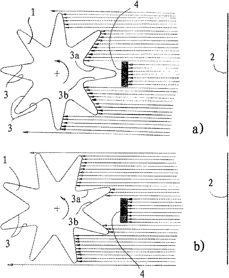
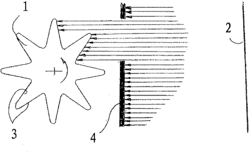
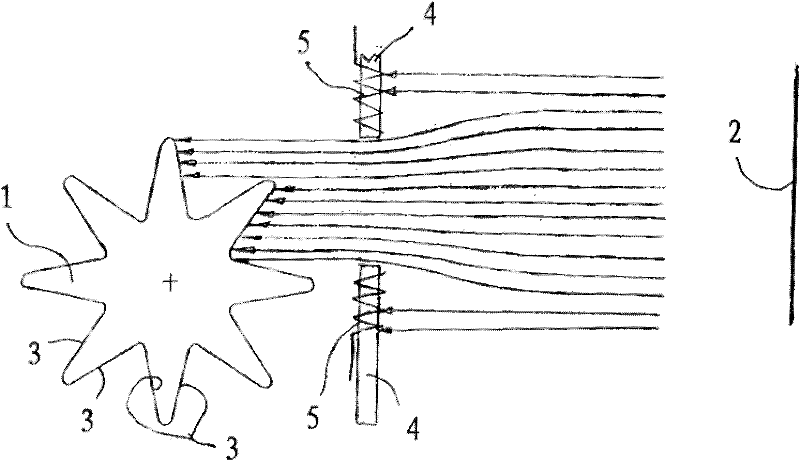
[0015] The coating system shown in the drawing is used for the tooth flank coating of a gear 1 and comprises a coating source 2 which emits a coating in the form of an ionized plasma stream in the direction of the gear 1 The coating beam, which is ideally shown as parallel in the figure, is actually substantially diffuse. In a magnetic and / or electric field, for example by applying a voltage to the gear 1 , the plasma particles are accelerated so strongly that they strike the tooth flank 3 with high kinetic energy and form a firmly adhering, hard coating there.

[0016] During the coating process, the gear 1 rotates about the gear axis, so that all tooth flanks 3 can enter successively into the coating jet of the coating source 1 . At this time, the orientation of the tooth surface 3 relative to the beam direction is changing, so the impact angle of the plasma particles on the tooth surface 3 is also changing. In the region of revolution in which the tooth flanks of the gear ...


PUM


Abstract

The invention relates to a method and a device for coating a functional surface of a component having a symmetrical tooth shape, in particular a tooth flank (3) of a gear (1), comprising emitting a coating substance in the form of charged particles in the direction of the component and relatively The revolving coating source (2) of the component achieves, according to the invention, a high-quality functional surface coating of the component in a technically simple manner, that is, the contact between the component (1) and the coating source (2) Transversely to the beam direction, the beam path is provided with a baffle (4) which shields the component from the coating jet in the swivel region in which the functional surface is oriented obliquely relative to the beam direction.

Description

technical field [0001] The invention relates to a method and a device for coating the functional surfaces of a component with a symmetrical tooth profile, in particular a tooth surface of a gear, comprising a coating in the form of a rotating relative to said component and emitting charged particles in the direction of said component The coating source of substance, as described in the preamble of claim 1 or 8. Background technique [0002] It is well known that in order to improve the wear resistance, the tooth surfaces of gears are coated in the vapor deposition method in such a way that a plasma generated by a coating source such as a graphite base and accelerated in an electric or magnetic field is They are emitted onto the tooth flank, where they accumulate in the region of the tooth flank close to the edge, where the graphite plasma particles are converted into a particularly hard, diamond-like coating. In addition to the ionization degree and energy of the plasma par...

Claims


Application Information

Patent Timeline
Patent Type & Authority Applications(China)
IPC IPC(8): C23C14/04C23C14/50
CPCC23C14/505C23C14/04C23C14/044
Inventor J·施纳格尔S·库尔萨韦H-J·沙伊贝V·魏纳赫特
Owner BAYERISCHE MOTOREN WERKE AG
Why Eureka
Try Eureka