Convex asymmetric corrugated tube heat exchanger

An asymmetric and corrugated tube technology, which is applied in the field of corrugated tube heat exchangers and convex asymmetric corrugated tube heat exchangers, can solve the problem of low comprehensive heat transfer efficiency and unsuitable gas-steam heat exchange It can improve the overall heat transfer efficiency, smooth the fluid flow, and reduce the flow dead zone.

Active Publication Date: 2011-12-14
HARBIN INST OF TECH
View PDF8 Cites 9 Cited by
  • Summary
  • Abstract
  • Description
  • Claims
  • Application Information

AI Technical Summary

Problems solved by technology

[0008] The purpose of the present invention is to solve the problems that the existing corrugated tube heat exchangers have low comprehensive heat transfer efficiency, cannot be applied to gas-steam heat exchange, and are difficult to detect in service, and then provide a convex asymmetric type Corrugated tube heat exchanger

Method used


Image

  • Convex asymmetric corrugated tube heat exchanger
  • Convex asymmetric corrugated tube heat exchanger
  • Convex asymmetric corrugated tube heat exchanger

Examples


specific Embodiment approach 1

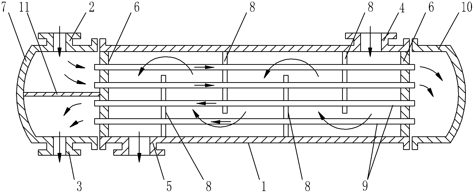
[0015] Specific implementation mode one: combine figure 1 , figure 2 , image 3 and Figure 4 To illustrate this embodiment, the convex asymmetric corrugated tube heat exchanger of this embodiment includes a shell 1, a cold medium inlet pipe 2, a cold medium outlet pipe 3, a heat medium inlet pipe 4, a heat medium outlet pipe 5, two A tube plate 6, a first head 7, a second head 10, a horizontal partition 11, a plurality of baffles 8 and a plurality of heat exchange tubes 9, and a tube plate 6 is respectively installed on the inner walls of both ends of the shell 1 A first seal head 7 is installed on one end surface of the shell 1, a second seal head 10 is installed on the other end surface of the shell 1, a heat medium inlet pipe 4 is arranged on the top of the shell 1, and a heat medium inlet pipe 4 is arranged on the bottom of the shell 1. The heat medium outlet pipe 5, the first head 7 is provided with a horizontal partition 11, the top of the first head 7 is provided w...

specific Embodiment approach 2

[0016] Specific implementation mode two: combination figure 1 , figure 2 and image 3 To describe this embodiment, the convex asymmetrical corrugated pipe of this embodiment is made of carbon steel, alloy steel or stainless steel. Such setting is convenient for processing and forming, and has low cost and long service life. Other compositions and connections are the same as in the first embodiment.

specific Embodiment approach 3

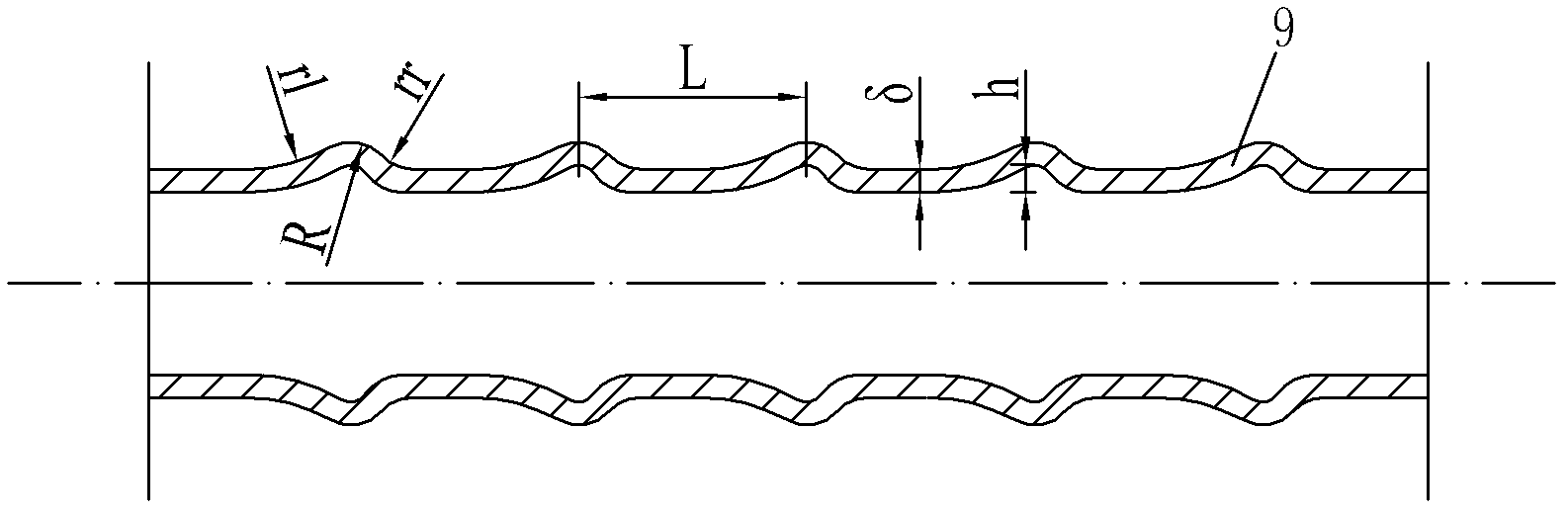
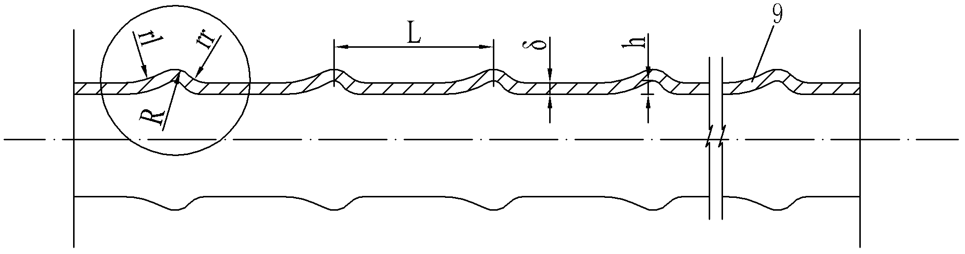
[0017] Specific implementation mode three: combination figure 2 , image 3 and Figure 4 To describe this embodiment, the outer wall of the convex asymmetric corrugated tube in this embodiment is located on the outflow side. The radius of curvature rl of the arc surface is 10mm to 30mm. This setting eliminates the flow dead zone in the rising area of ​​the corrugated joints, and makes the fluid flow smoother and the flow resistance smaller. Compared with the corresponding symmetrical corrugated tubes, the heat transfer is almost unchanged, but the overall heat transfer efficiency is greatly improved. . Other compositions and connections are the same as those in Embodiment 1 or Embodiment 2.


PUM


Abstract

The invention discloses an external-convex-type asymmetrical wave node pipe heat exchanger, and relates to a wave nod pipe heat exchanger for solving problems that the comprehensive heat transfer efficiency is low for the existing wave node pipe heat exchanger, the heat exchanger can not applied to gas-steam heat exchange, and the in-service detection is difficult. Each heat exchange pipe (9) provided by the invention is an external-convex-type asymmetrical wave node pipe; the curvature radius (rr) of the outer side wall, positioned on the circular arc surface of an going flow side, of the external-convex-type asymmetrical wave node pipe is less than the curvature radius (r1) of the outer side wall, positioned at the circular arc surface of an incoming side, of the external-convex-type asymmetrical wave node pipe; the curvature radius (R) of the external circular arc surface of a circular arc protrusion of the external-convex-type asymmetrical wave node pipe is 5mm; the distance (L) between two adjacent circular arc protrusions on the external-convex-type asymmetrical wave node pipe is 40mm-50mm; the top depth (h) of the circular arc protrusions of the external-convex-type asymmetrical wave node pipe is 2mm-4mm; and the wall thickness (delta) of the external-convex-type asymmetrical wave node pipe is 2mm-3mm. The heat exchanger provided by the invention is especially suitable for the gas-steam heat exchange.

Description

technical field [0001] The invention relates to a corrugated tube heat exchanger, in particular to an outwardly convex asymmetrical corrugated tube heat exchanger, which belongs to the technical field of heat exchange process equipment. Background technique [0002] Since the outbreak of the energy crisis in the 1970s, research on the strengthening of traditional heat exchanger equipment has gradually emerged, and mainly focused on two major directions; one is to develop new types of heat exchangers, such as plate type, spiral plate type, vibrating coil type, plate type, etc. The design idea of ​​these heat exchangers is to improve the heat exchange efficiency as much as possible; the second is to take strengthening measures for the traditional shell-and-tube heat exchanger. Specifically, it is to replace the original light pipe with various special-shaped pipes. The more commonly used ones are horizontal grooved tubes, zoom tubes, inner finned tubes, and inserting reinforc...

Claims


Application Information

Patent Timeline
Patent Type & Authority Applications(China)
IPC IPC(8): F28F1/08F28F21/08
Inventor 李炳熙韩怀志李凤臣于碧涌
Owner HARBIN INST OF TECH
Why Eureka
Try Eureka