Eureka AIR delivers breakthrough ideas for toughest innovation challenges, trusted by R&D personnel around the world.

Circuit board, circuit board assembly and semiconductor device

A technology for circuit boards and semiconductors, applied in semiconductor devices, printed circuit parts, circuits, etc., can solve problems such as the inability to reduce the stress at the joints of raised electrodes.

Inactive Publication Date: 2011-12-14
FUJITSU LTD
View PDF6 Cites 5 Cited by
  • Summary
  • Abstract
  • Description
  • Claims
  • Application Information

AI Technical Summary

Problems solved by technology

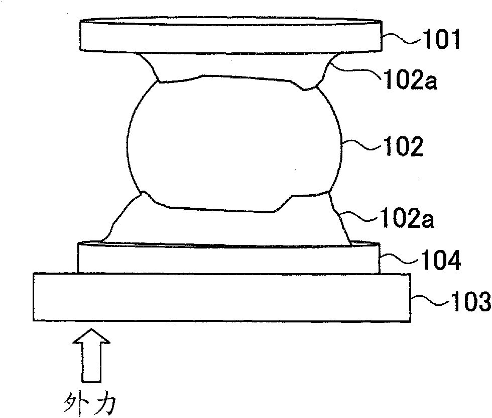
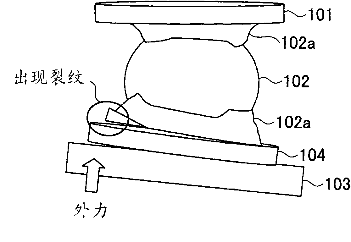
However, this mounting structure cannot relieve the stress generated by the protruding electrode junction

Method used


Image

  • Circuit board, circuit board assembly and semiconductor device
  • Circuit board, circuit board assembly and semiconductor device
  • Circuit board, circuit board assembly and semiconductor device

Examples


Embodiment Construction

[0032] Embodiments of the present invention will be described below with reference to the accompanying drawings.

[0033] figure 2 is a cross-sectional view of a circuit board assembly according to one embodiment of the present invention. Such as figure 2 As shown, the circuit board assembly includes a circuit board 2 , a semiconductor device 4 and a passive device 6 (such as a resistor, a capacitor, etc.), so that the semiconductor device 4 and the passive device 6 are mounted on the circuit board 2 . The circuit board 2 includes wiring both on its surface and inside. The semiconductor device 4 includes an electrode 4c. The electrodes 4c are bonded to the corresponding electrode pads 2a of the circuit board 2 through solder bumps 8 as bonding members.

[0034]The circuit board 2 is, for example, a multi-layer board formed by using an organic board (such as glass epoxy resin). On the surface of the circuit board 2, electrode pads 2a for mounting the semiconductor device...


PUM


Abstract

The present invention relates to circuit boards, circuit board assemblies and semiconductor devices. The disclosed circuit board includes: a substrate including wiring; a plurality of electrode pads formed on a surface of the substrate and to be combined with external connection terminals of electronic components; and grooves formed on the surface of the substrate around each electrode pad on the In addition, the groove forms a void that separates the lower portion of the electrode pad on the substrate from surrounding elements.

Description

technical field [0001] The present invention relates to a circuit board, a circuit board assembly, and a semiconductor device on which electronic parts are to be mounted. Background technique [0002] An electronic device generally includes a circuit board (may also be referred to as a "wiring substrate" or the like) on which electronic components such as a semiconductor device are mounted. Recently, such electronic devices have been miniaturized in size. Therefore, electronic components are required to be mounted on circuit boards at a higher density, and the size of the circuit boards has also become smaller. As a result, the size of the mounting structure for mounting electronic components on the circuit board is also smaller. [0003] Solder bumps are generally used as joining components for mounting semiconductor devices on circuit boards. With solder bumps, a solder bond can be achieved that not only provides an electrical connection between the semiconductor device...

Claims


Application Information

Patent Timeline
IPC IPC(8): H01L23/492
CPCH05K2201/10734H05K3/3436H05K1/0271H05K2201/09036H05K2203/041H01L2224/16225Y02P70/50
Inventor 小林弘冈田徹江本哲北岛雅之
Owner FUJITSU LTD
Why Eureka
Eureka Blog
Learn More