Riveting machine

A technology of riveting machine and riveting die, which is applied in the direction of connection, electrical components, circuits, etc., can solve the problems of difficult quality management, poor riveting, and many processing personnel, so as to improve the efficiency of riveting operations, ensure high accuracy, and ensure the riveting position. precise effect

Inactive Publication Date: 2011-12-14
DONGGUAN KECHENDA ELECTRONICS TECH
View PDF7 Cites 2 Cited by
  • Summary
  • Abstract
  • Description
  • Claims
  • Application Information

AI Technical Summary

Problems solved by technology

For example, for an HDMI connector, which includes two sets of terminals, the existing riveting machine system first performs riveting processing on one row of terminals, and then performs riveting processing on the other group of terminals through the next process. Therefore, the entire peeling process is completed. There are many equipments that need to be applied in the process, and there are correspondingly many processing personnel. In this way, the production cost is high, it is difficult to further improve the production efficiency, and the quality management is also difficult to control. In particular, the riveting machine in the prior art, In the actual production process, it is easy to have poor riveting caused by inaccurate riveting position or weak riveting, which seriously affects the performance of connectors and corresponding electronic products.

Method used


Image

  • Riveting machine
  • Riveting machine
  • Riveting machine

Examples


Embodiment Construction

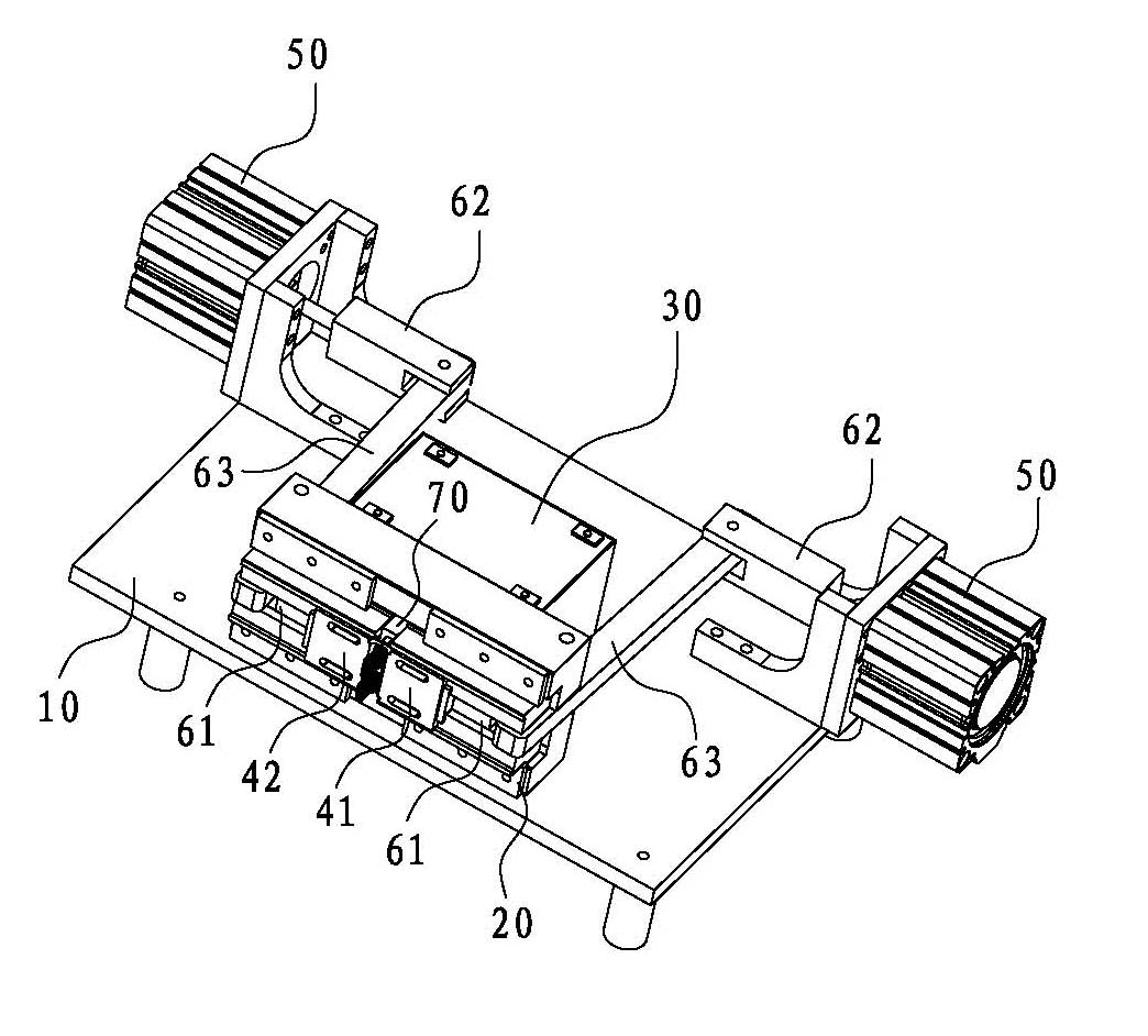
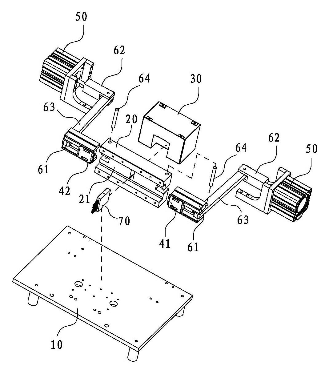
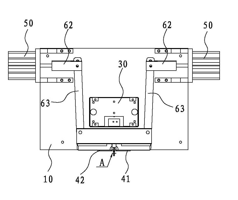
[0042] See Figure 1 to Figure 9 As shown, it shows the specific structure of the preferred embodiment of the present invention, including an organic base 10, a fixing frame 20 installed on the base 10, and an electric control device 30, wherein the electric control device 30 is connected to the lower The driving device 50 is used to control the operation of the driving device 50.

[0043] combine figure 2 , Figure 5 and Image 6 As shown, the fixed frame 20 is provided with a chute 21 extending in the left and right direction, and the fixed frame 20 is provided with a connector installation part 70, the connector installation part 70 is detachably installed in the fixed frame 20, the connection Two positioning grooves 71 extending along the front and rear directions for installing the connector are opened on the connector mounting part 70, and the two positioning grooves 71 are arranged in a row along the vertical direction, and the two upper positioning grooves 71 are a...


PUM


Abstract

The invention discloses a riveting machine comprising a baseframe, as well as a fixed frame and an electric control device which are mounted on the baseframe, wherein a sliding chute extending along the left-and-right direction is formed on the fixed frame, a positioning groove which extends along the front-and-back direction and is used for mounting a connector is formed at the middle of the sliding chute, a first riveting die is mounted in the sliding chute on the left side of the positioning groove, a second riveting die is mounted in the sliding chute on the right side of the positioning groove, a transmission mechanism and a driving device for providing original power for the transmission device are arranged aiming at each of the first riveting die and the second riveting die, and each transmission device is used for pushing the first riveting die or the second riveting die to move left and right in the sliding chute, therefore, under the coordination of all the devices, the first riveting die and the second riveting die move towards each other and prop against the two groups of terminals to be riveted till the terminals are firmly riveted with corresponding wires, the riveting operation can be fast completed on the two groups of terminals and the corresponding wires of the same connector once, and the riveting position is precise.

Description

technical field [0001] The invention relates to the technical field of machinery for riveting wires and connector terminals, in particular to a riveting machine capable of quickly completing the riveting operation of two groups of terminals of the same connector at one time, and the riveting position is precise. Background technique [0002] At present, as a signal connection device, the connector is widely used in various electronic products, therefore, the production and quality of the connector are particularly important. [0003] In recent years, a riveting machine has appeared, which replaces the most primitive manual operation mode with a mechanical operation mode. In comparison, it can quickly rivet the stripped wire end and the terminal of the connector, which is suitable for mass production , greatly improving the riveting efficiency. For example, for an HDMI connector, which includes two sets of terminals, the existing riveting machine system first performs riveti...

Claims


Application Information

Patent Timeline
Patent Type & Authority Applications(China)
IPC IPC(8): H01R43/048
Inventor 骆阳旭
Owner DONGGUAN KECHENDA ELECTRONICS TECH
Why Eureka
Try Eureka