
Permanent magnet machines specifically generators for wind turbines

A technology of wind turbines and permanent magnets, applied in wind power generation, electromechanical devices, magnetic circuits, etc., can solve problems such as increasing harmonic components, torque fluctuations, and structural noise of wind turbines

Inactive Publication Date: 2011-12-14
SIEMENS AG
View PDF4 Cites 0 Cited by
  • Summary
  • Abstract
  • Description
  • Claims
  • Application Information

AI Technical Summary

Problems solved by technology

Changes in reluctance cause changes in force or torque on the rotor and result in torque ripple
Such torque ripple adds unnecessary harmonic components, which leads to torque ripple in the operation of permanent magnet machines
Although the net torque ripple is zero, the cogging torque causes noise and additional stress on the wind turbine structure

Method used


Image

  • Permanent magnet machines specifically generators for wind turbines
  • Permanent magnet machines specifically generators for wind turbines
  • Permanent magnet machines specifically generators for wind turbines

Examples


Embodiment Construction

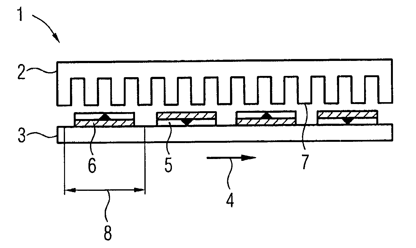
[0022] figure 1 A conventional permanent magnet machine 1 is shown, which is used as a generator for a wind turbine. The stationary stator 2 is usually included in the nacelle, which is located on top of the tower of the wind turbine. The rotor 3 moves rotatably around the stator 2 . In fact, stator 2 and rotor 3 are slightly bent, but in figure 1 In the schematic diagram of , the stator 2 and the rotor 3 are represented in a flat projection. Arrow 4 shows the circumferential direction in which the rotor 3 turns.

[0023] can from figure 1 It can be seen from the figure that a plurality of permanent magnets 5 , 6 are located on one side of the rotor 3 . The stator 2 includes a plurality of stator teeth extending vertically toward the rotor 3 . Each stator tooth 7 has a stator coil (in figure 1 not shown). Each of the plurality of permanent magnets 5, 6 forms a pole 8, all alternating in succession, ie a permanent magnet with a north pole on top followed by a permanent ...


PUM


Abstract

A permanent magnet machine, in particular a generator for a wind turbine, comprising: - a stator with a plurality of induction coils; - a rotor, rotatable around the stator, with a plurality of permanent magnets arranged in circumferential direction forming a number of poles, whereby each pole (12, 23, 25, 29) comprises two or more neighbouring magnets (13, 14, 15, 16, 18, 19, 21, 22, 26, 30) magnetised in the same direction.

Description

technical field [0001] The present invention relates to permanent magnet machines, in particular generators for wind turbines, comprising a stator with a plurality of induction coils, a rotor rotatable around the stator, said rotor having a plurality of permanent magnets extending circumferentially Orientation is set to form multiple poles. Background technique [0002] A wind turbine has a rotor shaft which is part of a generator which produces electricity during the movement of the rotor relative to the stator of a permanent magnet machine which acts as a generator. The stator includes a plurality of coils, and the rotor includes a plurality of permanent magnets to induce a voltage when the rotor rotates. [0003] Permanent magnet machines are generally subject to a result of the interaction between the permanent magnets of the rotor and the stator coil former, known as cogging torque. A conventional stator includes a plurality of teeth or slots for the stator coils. Th...

Claims


Application Information

Patent Timeline
Patent Type & Authority Applications(China)
IPC IPC(8): H02K1/27
CPCH02K7/183Y02E10/725H02K7/1838H02K1/278Y02E10/72
Inventor S.泽默
Owner SIEMENS AG
Features
  • Generate Ideas
  • Intellectual Property
  • Life Sciences
  • Materials
  • Tech Scout
  • Unparalleled Data Quality
  • Higher Quality Content
  • 60% Fewer Hallucinations
Learn More