A Multi-system Optical Transceiver Fiber Access System

A technology of optical fiber access and optical transceivers, applied in transmission systems, electromagnetic wave transmission systems, electrical components, etc., can solve problems such as limited capacity, unstable signals, waste of resources, etc., and achieve reduced quantity and configuration, less useless signals, and networking simple effect

Inactive Publication Date: 2011-12-14
JIALV COMM EQUIP SHANGHAI
View PDF5 Cites 10 Cited by
  • Summary
  • Abstract
  • Description
  • Claims
  • Application Information

AI Technical Summary

Problems solved by technology

[0003] (1) Waste of resources: Operators separately purchase optical fiber equipment such as CDMA, GSM, DCS, WCDMA, TDSCDMA, etc.
This will lead to an increase in operating costs and construction difficulties, and problems such as redundant construction caused by operators building their own coverage systems will become more and more prominent
[0004] (2) Capacity: Some buildings such as supermarkets, conference centers, etc., due to the excessive user density, the noise at the bottom of the CDMA network users is greatly increased, and the GSM congestion is serious, resulting in limited capacity
[0005] (3) In terms of quality: due to frequency interference, pilot pollution, and ping-pong effects, the signal in the cell is unstable, the voice quality is difficult to guarantee, and even call drops occur

Method used


Image

  • A Multi-system Optical Transceiver Fiber Access System
  • A Multi-system Optical Transceiver Fiber Access System

Examples


Embodiment Construction

[0021] The present invention will be described in detail below in conjunction with the accompanying drawings and specific embodiments.

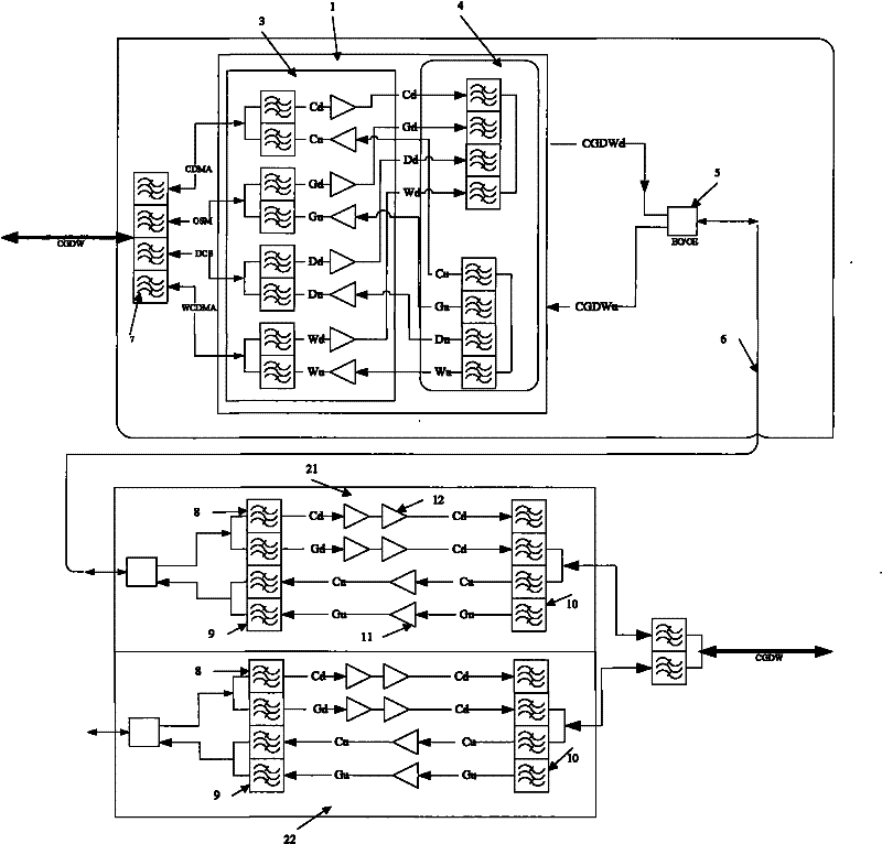
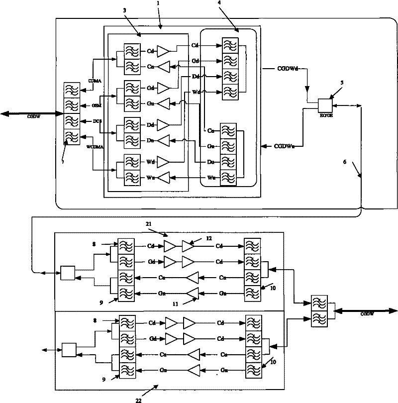
[0022] Such as figure 1 As shown, a multi-system optical terminal fiber access system includes a near-end unit 1, a remote unit, an optical fiber module 5, and an optical fiber cable 6. The near-end unit 1 is connected to the optical fiber module 5, and the optical fiber module 5 Connect with the near-end machine through the optical fiber line 6.

[0023] The near-end machine 1 includes a multi-system combining platform 7, a power amplifier driver module 3, and a four-frequency combiner 4, and the multi-system combining platform 7, the power amplifier driver module 3, and the four-frequency combiner 4 are sequentially connected . The power amplifier driver module 3 includes a CDMA driver module, a GSM driver module, a DCS driver module, and a WCDMA driver module. The CDMA drive module, GSM drive module, DCS drive module and WCDMA drive mod...


PUM


Abstract

The invention relates to a multi-system optical fiber access system for optical terminals, which includes a near-end computer, a remote computer, an optical fiber module, and an optical fiber cable. machine connection. Compared with the prior art, the present invention has the advantages of less useless signals, low cost, simple networking and the like.

Description

technical field [0001] The invention relates to an optical fiber access system of an optical terminal, in particular to a multi-system optical terminal optical fiber access system. Background technique [0002] The large-scale growth of mobile communication users makes the scale of the wireless network larger and larger, and the requirements for the quality of the network are also higher and higher. However, no matter what kind of wireless communication coverage area will produce weak signal areas or blind areas. Some remote areas, special places (tunnels, subways, large buildings, etc.) usually choose the economical and effective equipment of optical fiber repeater to solve the problem of signal coverage in these places. However, operators in the mobile market all strive to obtain good Customers will actively use a large number of indoor coverage system optimization work for the above-mentioned places. In order to compete for traffic volume and develop new traffic volume, ...

Claims


Application Information

Patent Timeline
Patent Type & Authority Applications(China)
IPC IPC(8): H04B10/14H04B10/12H04B10/27
Inventor 许汉铭
Owner JIALV COMM EQUIP SHANGHAI
Why Eureka
Try Eureka