A metal creep forming die

A mold and metal technology, applied in the field of metal sheet creep deformation mold, can solve the problems of high mold processing cost, long design and manufacturing cycle, etc., to reduce the cost of mold trial and avoid height errors.

Active Publication Date: 2011-12-21
CENT SOUTH UNIV
View PDF7 Cites 29 Cited by
  • Summary
  • Abstract
  • Description
  • Claims
  • Application Information

AI Technical Summary

Problems solved by technology

[0004] In order to solve the technical problems that the existing creep forming mold needs to be modified many times before the mold is finalized, the mold processing cost is high, and the design and manufacturing cycle is long, the invention provides a flexible mold without repeated machining. Adjusting the curvature characteristics of the mold surface can greatly reduce the mold cost of the creep aging forming component, and at the same time shorten the mold design and manufacturing cycle of the metal creep forming mold

Method used


Image

  • A metal creep forming die
  • A metal creep forming die
  • A metal creep forming die

Examples


Embodiment 1

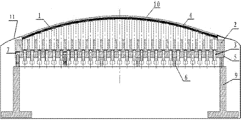
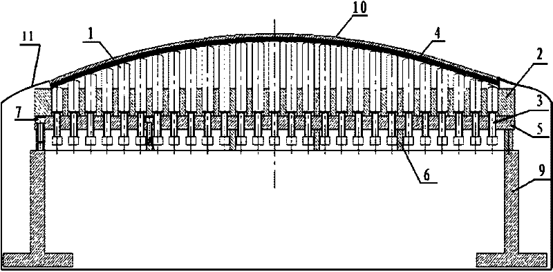
[0025] The plane size of the mold is B(400mm)×L(800mm), the ejector pin 1 has a diameter of 10mm, the two ends are hemispherical surfaces with a diameter of 10mm, the length is 50mm, and the distance between adjacent ejector pins 1 is 10mm; the thickness of the ejector pin fixing plate 2 is 20mm ; Each ejector rod 1 is equipped with a corresponding screw 3; the thickness of the screw fixing plate 5 is 50mm; the height of the rib 6 is 20mm; Taking the plane of ejector pin fixing plate 2 as a reference, the height array of ejector pin 1 is adjusted according to the radius of curvature in the L direction of 3000 mm, and the 0.5 mm thick 7075 aluminum alloy plate after solution quenching is used as the creep forming blank, and the mold and forming blank are used After the plastic bag 11 is sealed, vacuumize it, then place it in a normal-pressure heating furnace, and heat it at a rate of 150° C. for 16 hours. During the heating process, continue to vacuumize the sealed bag. Unload ...

Embodiment 2

[0027]The plane size of the mold is B(1600mm)×L(3900mm), the diameter of ejector pin 1 is 50mm, and the two ends are hemispherical surfaces with a diameter of 50mm, and the distance between adjacent ejector pins 1 is 250mm; the thickness of ejector pin fixing plate 2 is 120mm; The ejector rods 1 are equipped with corresponding screw rods 3; the thickness of the screw rod fixing plate 5 is 120mm; the height of the reinforcing rib 6 is 100mm; Taking the plane of the ejector pin fixing plate 2 as a reference, the height array of the ejector pin 1 is adjusted according to the radius of curvature in the L direction of 5000 mm, and the 100 mm thick 7075 aluminum alloy plate after solution quenching is used as the creep forming blank, and the mold and the forming blank are made of plastic After the bag 11 is sealed, vacuumize it, then place it in an 8MPa pressure tank, and heat it at 150°C for 16 hours, and continue to vacuumize the sealed bag during the heating process. Unload after...

Embodiment 3

[0029] Die plane size is B(400mm)×L(800mm), ejector pin 1 has a diameter of 20mm, both ends are hemispherical surfaces with a diameter of 20mm, the distance between adjacent ejector pins 1 is 50mm; the thickness of ejector pin fixing plate 2 is 20mm; each The ejector rods 1 are equipped with corresponding screw rods 3; the thickness of the screw fixing plate 5 is 50mm; the height of the reinforcing rib 6 is 50mm; Taking the plane of the ejector pin fixing plate 2 as a reference, adjust the height array of the ejector pin 1 according to the radius of curvature in the L direction of 3000mm and the radius of curvature in the B direction of 1500mm, and use a 10mm thick 2024 aluminum alloy plate after solution quenching as the creep forming blank. Seal the mold and the forming blank with a plastic bag 11 and then vacuumize it, then place it in a 4MPa pressure tank and heat it at 185°C for 24 hours, and continue to vacuumize the sealed bag during the heating process. Unload after he...


PUM

PropertyMeasurementUnit
diameteraaaaaaaaaa
lengthaaaaaaaaaa
thicknessaaaaaaaaaa

Abstract

The invention discloses a metal creep forming die. The metal creep forming die comprises an ejector rod, a threaded rod, an ejector rod fixing plate, a threaded rod fixing plate, a reinforcing rib, a height adjusting cushion block and a molded surface base plate, wherein the ejector rod is arranged in a cylindrical hole of the ejector rod fixing plate; the threaded rod is arranged in a threaded hole of the threaded rod fixing plate and is used for controlling the height of the ejector rod to form the required molded surface array; the reinforcing rib is arranged at the bottom of the fixing plate so as to enhance deformation resistance of the die; the height adjusting cushion block is arranged at the bottom of the reinforcing rib so as to adjust the horizontal height of the die; one layer of molded surface base plate is paved above the ejector rod array and is used for transitioning the discrete dot matrix surface into the required smooth curved surface; and the molded surface base plate may be an aluminum plate, a steel plate or a steel aluminum composite plate. In the die provided by the invention, the molded surface base plate can contact with all the ejector rod dot matrixes, so that the waviness of a creep formed member is less than 0.005 and good member molded surface quality is achieved; and the die process cost caused by that a fixed curvature characteristic integrated type structure die and a rib plate type split structure die are required to be modified repeatedly is avoided, so that die trial cost can be greatly reduced.

Description

technical field [0001] The invention relates to a mold, in particular to a metal plate creep forming mold used in metal material processing engineering. Background technique [0002] The integral wall panels that meet the design requirements of aerodynamic curvature have outstanding advantages such as high structural efficiency, easy realization of equal-strength design, and good sealing performance. They are important components for manufacturing aerospace and transportation equipment. Integral panel creep aging forming is a processing method that uses the creep (or stress relaxation) deformation and aging strengthening properties of metals to simultaneously perform the forming and aging strengthening heat treatment processes of components. The general process of using creep aging forming technology to manufacture integral wall panels is as follows: ①Design and manufacture molds according to the geometric dimensions and curvature characteristics of the required wall panels;...

Claims


Application Information

Patent Timeline
Patent Type & Authority Applications(China)
IPC IPC(8): B21D26/031
Inventor 邓运来张劲吴阳赵建华尹喜生龙旭初唐露华李思宇杨金龙陈愿情蔺永诚湛利华张新明
Owner CENT SOUTH UNIV
Why Eureka
Try Eureka