Vacuum casting device

A technology of vacuum casting and cooling device, applied in the field of vacuum casting device, can solve the problems of inefficient recovery and the like

Active Publication Date: 2011-12-21
TOSHIBA CLIENT SOLUTIONS CO LTD
View PDF6 Cites 5 Cited by
  • Summary
  • Abstract
  • Description
  • Claims
  • Application Information

AI Technical Summary

Problems solved by technology

As a result, the release agent passes through the release agent recovery ...

Method used


Image

  • Vacuum casting device
  • Vacuum casting device
  • Vacuum casting device

Examples


Embodiment Construction

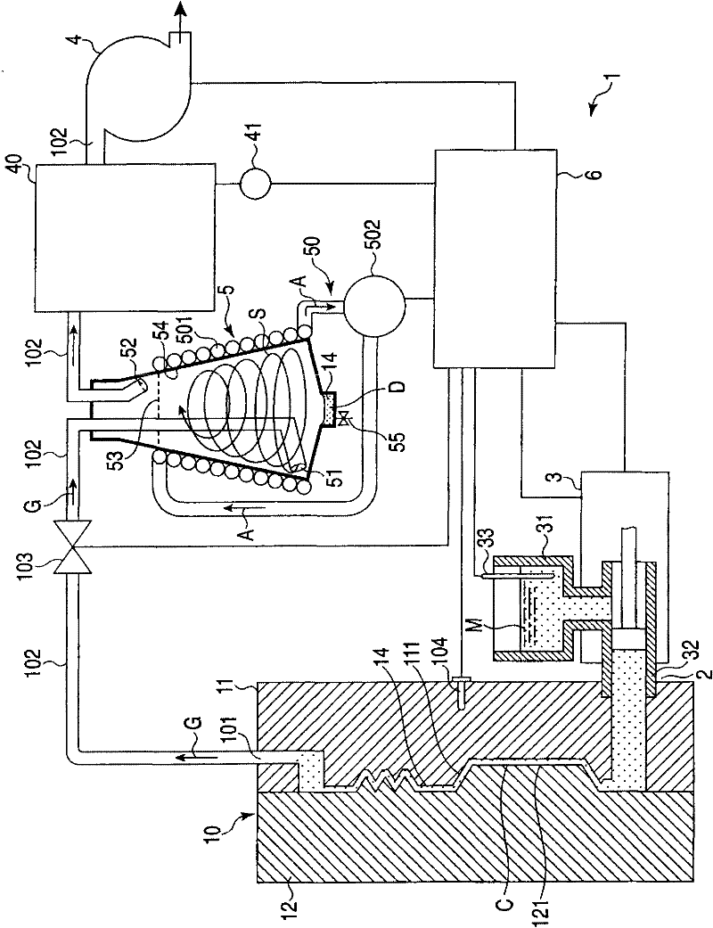
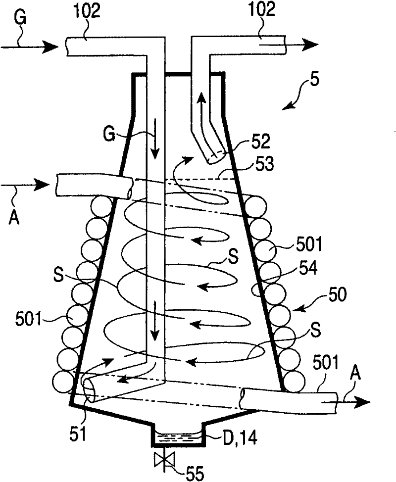
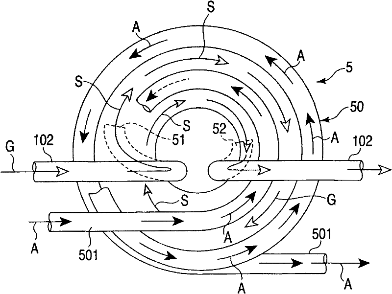
[0012] refer to Figure 1 to Figure 3 The vacuum casting device of the first embodiment will be described. figure 1 The shown vacuum casting device 1 has a mold 10, a plunger 3, a molten metal tank (molten metal tank) 31, a suction pipe 102, a valve (valve) 103, a vacuum pump 4, a vacuum tank 40, a release agent recovery machine 5, a cooling device 50, and control device 6. The mold 10 is divided into a first mold 11 and a second mold 12 along the dividing line of the product. The first mold 11 and the second mold 12 have a first parting surface 111 and a second parting surface 121 at joint surfaces. The first parting surface 111 and the second parting surface 121 form a cavity C for casting a product by joining the first mold 11 and the second mold 12 together. A release agent 14 is coated on the inner surface of the cavity C. The mold 10 has a melt supply port 2 communicating with the cavity C and a suction port 101 .

[0013] Such as figure 1 As shown, the plunger 3 i...


PUM


Abstract

The vacuum casting device (1) has: a mold (10), a plunger (3), a vacuum pump (4), a release agent recovery machine (5), and a cooling device (50). The mold (10) is coated with a release agent (14) on the inner surface of the cavity (C). The plunger (3) supplies the melt (M) from the melt tank (31) to the cavity (C). The vacuum pump (4) sucks out the gas (G) including the vaporized release agent (14) inside the cavity (C). The release agent recovery machine (5) is connected in the middle of the piping (102) from the mold (10) to the vacuum pump (4), and the gas (G) guided by the piping (102) is generated from the lower suction port ( 51) Spiral swirling flow (S) towards the upper exhaust port (52). The release agent recovery machine (5) utilizes the centrifugal force of the swirling flow (S) to separate the liquefied release agent (14), and discharges the residual gas from the exhaust port (52). The cooling device (50) has a cooling pipe (501) wound on the outer peripheral wall (54) of the release agent recovery machine (5), and circulates the refrigerant (A) in the cooling pipe (501), thereby The peripheral wall (54) is cooled.

Description

technical field [0001] The invention relates to a vacuum casting device for coating a release agent on a mold. Background technique [0002] In die-cast molding in which casting is performed using a mold, a release agent may be applied to the inner surface of the cavity of the mold. There is a casting device that depressurizes a cavity with a vacuum pump when supplying a release agent, and supplies a powder release agent or a liquid mist (mist) by an atomizing device to the cavity. In any casting device, the remaining mold release agent is recovered by a low-pressure (cyclone) type mold release agent recovery machine installed between the mold and the vacuum pump. [0003] As existing documents, there are Japanese Laid-Open Patent Publication No. 2007-69218 and Japanese Patent No. 2927925 specification. [0004] When casting a metal material with a high casting temperature, since the set temperature of the mold and molten metal before casting is high, the mold release age...

Claims


Application Information

Patent Timeline
IPC IPC(8): B22D17/20B22D17/14
CPCB22D17/145B22D17/10
Inventor 平井裕一平尾浩昭中岛雄二
Owner TOSHIBA CLIENT SOLUTIONS CO LTD
Why Eureka
Try Eureka