Supercharge Your Innovation With Domain-Expert AI Agents!

led collimator device

A collimator, LED light source technology, applied in lighting devices, lighting device parts, instruments, etc., can solve non-compliance with requirements, reduce collection efficiency by collecting lenses, increase the size, complexity and cost of light-emitting devices, etc. problem, to achieve the effect of solving the divergence problem, simple manufacturing and low cost

Inactive Publication Date: 2011-12-21
SUZHOU DELPHI LASER +1
View PDF3 Cites 0 Cited by
  • Summary
  • Abstract
  • Description
  • Claims
  • Application Information

AI Technical Summary

Problems solved by technology

[0004] Use of separate and distinct collimators for each LED light source of the array increases the size, complexity and cost of the light emitting device and is not desirable
In addition, the large angle of refraction of the collection lens reduces the overall collection efficiency due to Fresnel loss and beam expansion at larger refraction angles

Method used


Image

  • led collimator device
  • led collimator device

Examples


Embodiment Construction

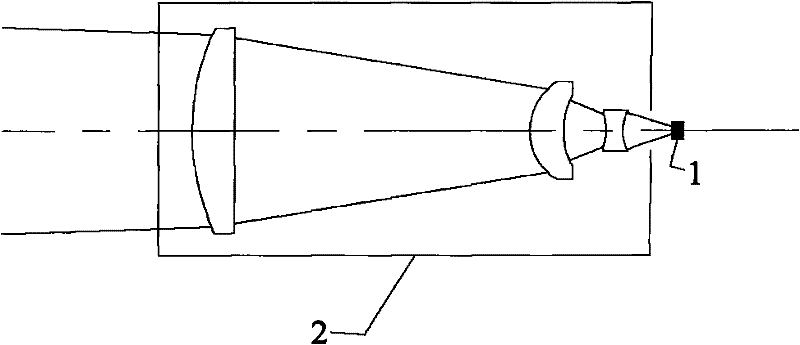
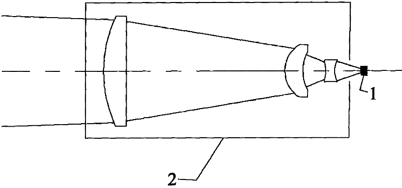
[0017] Such as figure 1 As shown, the LED collimator device includes an LED light source 1 and a collimator. The light collimator includes an optical lens and a lens barrel 2. The optical lens is placed in the lens barrel 2. There are 3 optical lenses arranged at intervals in sequence. The LED light source 1 is arranged at the incident window of the lens barrel 2, and the emission angle of the LED light source 1 is less than 60°.

[0018] The LED light source 1 can be a point light source or a surface light source, and the light emitted during its operation basically enters the incident window of the collimator. The collimator is designed as a barrel structure, and the light can obtain a uniform light intensity distribution within a certain range after passing through the collimator. The main direction of the incident light is parallel to the optical axis of the LED; the distance between the LED and the collimator of the light source is less than 1mm; the working distance of ...


PUM

PropertyMeasurementUnit
Launch angleaaaaaaaaaa

Abstract

The invention provides an LED collimator device, which includes an LED light source and a collimator. The light collimator includes an optical lens and a lens barrel. The optical lens is placed in the lens barrel, and the LED light source is arranged at the incident window of the lens barrel. The LED light collimator device can be used for the collimation of the LED light source used in the microscope, and can also be used for the collimation of the LED lighting source. The light emitted by it meets the Lambertian surface light source, and basically all of it is incident on the incident surface of the collimator element. . The device is simple to manufacture, low in cost and convenient to use, and effectively solves the problem of light divergence of LED lamps.

Description

technical field [0001] The invention relates to an LED collimator device, which is used for LED packaging to collect light emitted by the LED, and is also used for collimating the LED light source used in a microscope to generate a collimated light beam with uniform distribution of light intensity. Background technique [0002] Microscopes generally use halogen lamps as illumination sources, but halogen lamps have many defects such as short life and high heat generation; with the development of LED technology, more and more people use high-brightness LED lamps as the illumination source for microscopes. [0003] The LED collimation device collimates and focuses the divergent LED light to irradiate the observed object. Currently, many LED light generators employ multiple separate and distinct basic optical components, each of which is capable of efficiently collecting the very broad divergence of light produced by each LED light source. [0004] Using a separate and distinct...

Claims


Application Information

Patent Timeline
IPC IPC(8): G02B27/30G02B21/06F21V5/04F21Y101/02
Inventor 赵裕兴汪昊
Owner SUZHOU DELPHI LASER
Features
  • R&D
  • Intellectual Property
  • Life Sciences
  • Materials
  • Tech Scout
  • Unparalleled Data Quality
  • Higher Quality Content
  • 60% Fewer Hallucinations
Learn More