
Etching system

An etching system and permanent magnet technology, applied in the field of etching systems, can solve the problems of decreased electrode cleaning ability, particle collision probability, plasma concentration cannot be further increased, etc., and achieve the effect of increasing the collision frequency

Inactive Publication Date: 2014-04-16
XUZHOU GAPSS OE TECH
View PDF4 Cites 0 Cited by
  • Summary
  • Abstract
  • Description
  • Claims
  • Application Information

AI Technical Summary

Problems solved by technology

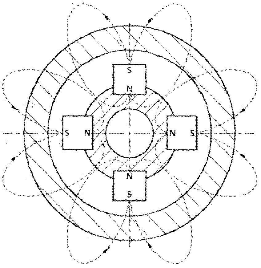
But the position of the magnetic field is relatively fixed (such as image 3 As shown), with the consumption of the upper electrode 14, the thickness becomes thinner, resulting in a decline in electrode cleaning ability; in addition, the direction of the magnetic field is also fixed, resulting in fixed magnetic force lines, so the particle collision probability and plasma (Plasma) concentration cannot be further improved

Method used


Image

  • Etching system
  • Etching system
  • Etching system

Examples


Embodiment Construction

[0040] In order to make the technical problems, technical solutions and advantages to be solved by the present invention clearer, the following will describe in detail with reference to the drawings and specific embodiments.

[0041] Such as Figure 4 As shown, the etching system of the embodiment of the present invention includes: a chamber 20 for accommodating plasma 28; a quartz disk 21 arranged above the chamber 20; a plurality of Permanent magnet 23; rotating mechanism 30, described rotating mechanism 30 drives the described plurality of permanent magnets 23 above the quartz disk 21 to rotate, and the magnetic field that described plurality of permanent magnets 23 produces is with the rotation of described plurality of permanent magnets 23 While rotating, the plasma 28 is in the magnetic field.

[0042] In this embodiment of the present invention, the etching system may further include: a first electrode 24 disposed between the quartz disk 21 and the permanent magnet 23,...


PUM


Abstract

The invention provides an etching system which comprises a cavity, a quartz disc, a plurality of permanent magnets and a rotating mechanism, wherein the cavity is used for containing plasma; the quartz disc is arranged above the cavity; the plurality of permanent magnets is arranged above the quartz disc; the rotating mechanism drives the plurality of permanent magnets to rotate; magnetic fields generated by the plurality of permanent magnets rotate along with the rotation of the plurality of permanent magnets; and the plasma is in the magnetic fields. According to the technical scheme of the invention, the collision frequency of particles can further be increased so that the degree of uniformity of the plasma is optimized and the concentration of the plasma also can be increased.

Description

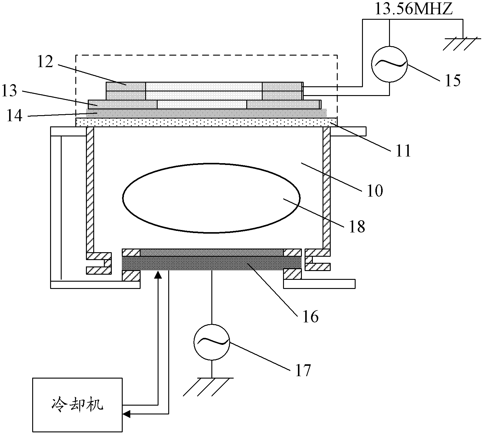
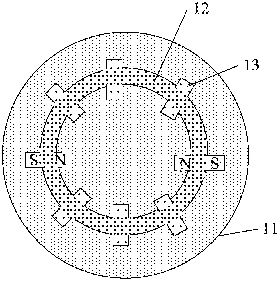
technical field [0001] The invention relates to etching technology in the LED field, in particular to an etching system. Background technique [0002] PSS (patterned substrate) dry etching in the LED field currently uses a high-density plasma ICP etching system, such as figure 1 , figure 2 with image 3 as shown, figure 1 A cross-sectional view of the current high-density plasma ICP etching system, figure 2 for figure 1 A top view of the system shown, image 3 for figure 1 The schematic diagram of the magnetic field lines of the system is shown, wherein the etching system includes: a cavity 10, a plasma 18 is placed in the cavity 10, a quartz disk 11 is arranged above the cavity 10, and an upper electrode 14 is arranged above the quartz disk 11 , above the upper electrode 14 is a permanent magnet 13 and a contactor 12, wherein the permanent magnet 13 is arranged above the quartz disk 11 in a fixed manner, the system also includes a lower electrode 16 arranged below ...

Claims


Application Information

Patent Timeline
Patent Type & Authority Patents(China)
IPC IPC(8): H01L21/306H01L33/00
Inventor 马擎天池玟霆李明亮
Owner XUZHOU GAPSS OE TECH
Learn More