A pre-twisted anti-skid damping spacer

A spacer and damping technology, applied in the field of spacer, can solve the problems of not being able to fix the wires, protect the wires, increase the stress, clamp the wires too tightly, etc., achieve easy control of the installation quality, and reduce stress concentration , the effect of preventing axial displacement

Inactive Publication Date: 2011-12-21
江苏华厦电力成套设备有限公司
View PDF0 Cites 7 Cited by
  • Summary
  • Abstract
  • Description
  • Claims
  • Application Information

AI Technical Summary

Problems solved by technology

[0004] However, because the wire is in the natural environment in the wild, the temperature changes with the seasons, and the thermal expansion and cooling of the wire will change the diameter of the wire, which will affect the holding force of the spacer to the wire to a certain extent; During operation, due to a variety of factors, its operating temperature also has a large change. The effect of this temperature change is similar to a thermal cycle, and it may eventually cause the clamp to hold the wire due to a drop in the bolt torque. Focus on descending
The decline of the holding force of the spacer on the conductor may directly affect the possible slippage of the spacer, which will cause the spacer to deviate from the optimal installation position of the design, thus failing to achieve the designed effect of fixing the conductor and protecting the line , and may even bring new dangerous vibrations and stress increases to the wires at a certain moment where the spacer bar is located, and even lead to faster fatigue of the wires, resulting in serious accidents and losses such as line damage
[0005] In addition, because the traditional spacer adopts a collet-type structure, the clamping and holding of the wire by the spacer is realized by bolts and nuts, fastening clamps and glands, and the force-bearing surface of the wire is limited to the clamp. Within the width, usually tens of millimeters, the stress area is too small, and there is a safety addiction to damage the wire due to stress concentration
The

Method used


Image

  • A pre-twisted anti-skid damping spacer
  • A pre-twisted anti-skid damping spacer
  • A pre-twisted anti-skid damping spacer

Examples


Embodiment Construction

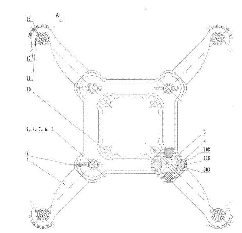
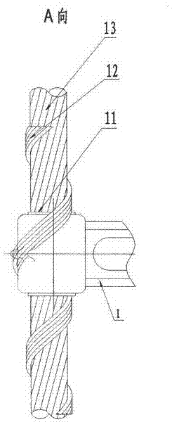
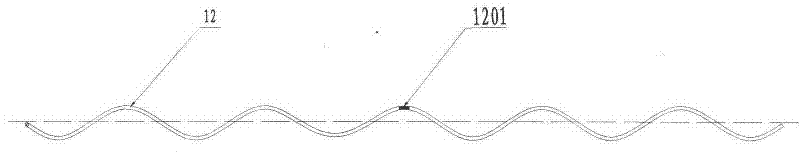
[0059] The invention is like Figure 1-23 As shown, it includes a bracket 2 and a wire clip 1. The wire clip 1 is arranged at the end corner of the bracket 2 for connecting the split wires 13, and the wire clip 1 also includes a pre-twisted wire 12; The head end of the connecting split wire 13 is in the shape of a hook 103, and the back of the hook 103 is provided with a positioning structure for positioning the pre-twisted wire 12; the tail end of the wire clip 1 and the end of the bracket The corner parts are connected by a damping limit device.

[0060] The damping limit device includes a cross hub 3, a damping rubber column 4, a hinge bolt assembly (a hinge bolt 5, a nut 6, a flat washer 7, a spring washer 8, a closing pin 9) and a limit safety pin 10;

[0061] The tail end of the wire clamp 1 is provided with a cylindrical cavity 108, the axis of the cylindrical cavity 108 is parallel to the axis of the hook 103 at the head end of the wire clamp 1, and the middle of the cavity...


PUM


Abstract

The invention relates to a pre-twisted anti-slip damping spacer bar. It includes a bracket and a wire clip, the wire clip is arranged at the end corner of the bracket for connecting the split wire, and the wire clip also includes a pre-twisted wire; the head end of the wire clip used to connect the split wire is hook-shaped, The back of the hook is provided with a positioning structure for positioning the pre-twisted wire; the tail end of the clamp is connected to the corner of the bracket through a damping and limiting device. The invention can be installed by bare hands, has the advantages of convenient installation, good reliability and easy control of installation quality.

Description

Technical field [0001] The invention relates to a spacer rod for ultra-high voltage and ultra-high voltage transmission lines, in particular to a pre-twisted anti-skid damping spacer rod. Background technique [0002] For long-distance, large-capacity UHV and UHV transmission lines, each phase conductor uses two, three, four, six, eight or more split sub-conductors. In order to meet the electrical performance, reduce the surface potential gradient, and in the case of a short circuit, electromagnetic force will not be generated between the wire harnesses to cause mutual attraction, collision, whiplash, or instant relative motion, but after the accident is eliminated, it can be restored to the design spacing state , It is necessary to ensure that the spacing between the sub-conductors of the split wire harness remains unchanged, for this reason, install spacers of appropriate specifications and numbers at appropriate positions in the span. The installation of wire spacers can also...

Claims


Application Information

Patent Timeline
IPC IPC(8): H02G7/12H02G7/14
Inventor 庄大清庄大宏郭树龙王建虎庄杰
Owner 江苏华厦电力成套设备有限公司
Why Eureka
Try Eureka