

Low braking loss permanent magnet motor
A braking loss, permanent magnet motor technology, applied in the magnetic circuit static parts, magnetic circuit rotating parts, magnetic circuit shape/style/structure, etc., to achieve the effect of reducing back electromotive force, reducing burden, and weak cogging effect
- Summary
- Abstract
- Description
- Claims
- Application Information
AI Technical Summary
Problems solved by technology
Method used
Image

Examples
Embodiment 1
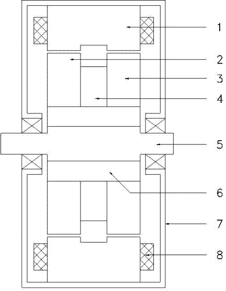
[0035] Low braking loss permanent magnet motor, the structure is as figure 1 shown. The stator is composed of a stator core 1 and a coil 8 . The stator core 1 is fixed on the frame 7, and the coil 8 forms the stator winding. The left salient pole rotor core 2, the permanent magnet 4, and the right salient pole rotor core 3 are axially arranged, and are fixed on the shaft 5 together with the bushing 6 to form a rotor. The salient poles on the left salient pole rotor core 2 and the right salient pole rotor core 3 are arranged opposite to each other in an axial direction.
[0036] After the stator winding is excited, a rotating magnetic field is generated to drive the rotor to rotate; in addition to the permanent magnet force, the reluctance torque similar to the switched reluctance motor is superimposed on the rotor. The driving method can be switching pulse or sinusoidal AC voltage.
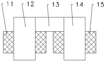
[0037] The stator core 1 in the figure is a segmented stator core. The part opposite to t...
Embodiment 2
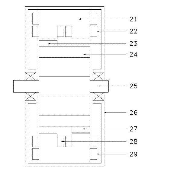
[0043] Low braking loss permanent magnet generators, such as image 3 shown. The segmented stator core 21 is fixed on the frame 26, and the coil 29 forms the stator winding. The right auxiliary coil 22 and the left auxiliary coil 28 are distributed on the two rotor segments of the stator core 21 and connected to form multi-phase auxiliary windings to form electromagnets. An equal number of N-pole permanent magnets 23 and S-pole permanent magnets 27 are fixed on the two ends of the rotor core 24 to form the N-pole and S-pole surface-mounted rotor cores; they are fixedly connected with the shaft 25 to form the rotor. The salient poles of the rotor formed by the permanent magnets of the N pole and the S pole are axially opposite and crossed. The magnetic field lines of the permanent magnets pass through the coils on the adjacent magnetic poles on the stator to form a closed loop. When rotating, the magnetic flux and direction in the coil will change, resulting in induced elect...
Embodiment 3
[0046] Permanent magnet motors with multiple rotor cores, such as Figure 4 shown. The stator includes a stator winding composed of a non-segmented stator core 31 and a coil 37; the rotor cores 34, 35, 36 are arranged at intervals in the axial direction, and the magnetic field directions of the permanent magnets 32 and 33 are opposite, and the magnetic field direction at the joint of the rotor core 35 is the same. Adjacent rotor cores are mutually opposite poles.
PUM
 Abstract
Description
Claims
Application Information