Check patentability & draft patents in minutes with Patsnap Eureka AI!

Direct drive rotary unit

A rotating device and direct drive technology, which is applied in the direction of electromechanical devices, magnetic circuit rotating parts, casings/covers/supports, etc., can solve the problem of compact and simple structure, easy damage of grating scale encoder, and difficulty in ensuring Rotor stiffness and other issues, to achieve the effect of simplifying the structure, ensuring high-speed rotation requirements, and reducing temperature rise

Active Publication Date: 2011-12-21
SUZHOU ACCURACY ASSEMBLY AUTOMATION CO LTD
View PDF6 Cites 8 Cited by
  • Summary
  • Abstract
  • Description
  • Claims
  • Application Information

AI Technical Summary

Problems solved by technology

[0007] In addition, there are disadvantages that the grating ruler (the patent is called non-contact precision circular grating) and the encoder (the patent is called non-contact reading head) are easily damaged, because it is the ability to resist external interference or influence. The fragile grating ruler and encoder are exposed, for details, please refer to the last two lines on page 3 of the patent specification
In addition, the patented solution is difficult to ensure the rigidity of the rotor (the patent is called the direct drive motor rotor), although it uses a high-precision and high-rigidity large-diameter one-way bearing (line 4, page 4 of the manual), and this bearing is a special Bearings are difficult to obtain from commercial channels. In addition, it is not only troublesome to connect the rotor to the inner ring of the bearing with long bolts, but also loses the compactness and simplicity of the structure.

Method used


Image

  • Direct drive rotary unit
  • Direct drive rotary unit
  • Direct drive rotary unit

Examples


Embodiment Construction

[0025] In order to enable the examiners of the patent office, especially the public, to understand the technical essence and beneficial effects of the present invention more clearly, the applicant will describe in detail the following in the form of examples, but none of the descriptions to the examples is an explanation of the solutions of the present invention. Any equivalent transformation made according to the concept of the present invention which is merely formal but not substantive shall be regarded as the scope of the technical solution of the present invention.

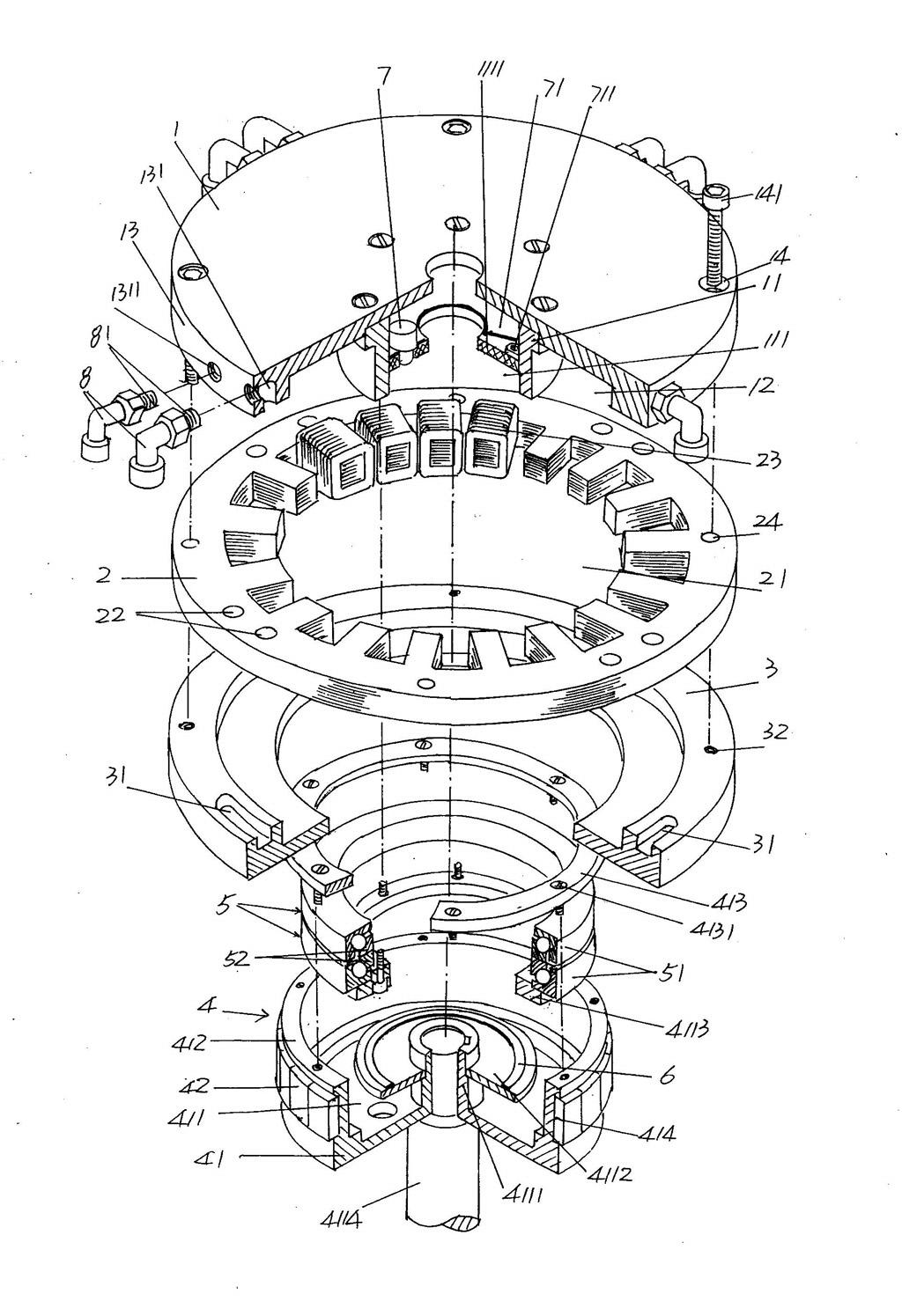
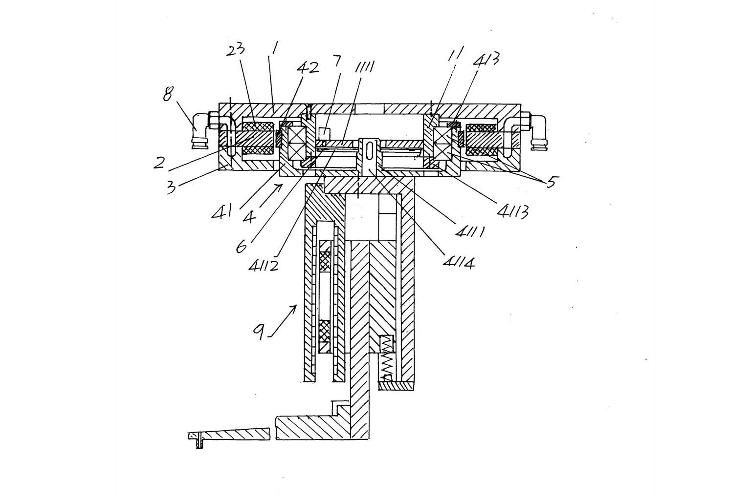
[0026] please see figure 1 , provides a casing 1 that constitutes the direct drive rotary device of the present invention, and the casing 1 can also be referred to as an upper cover, and directly or indirectly The bearing seat 11 is formed by the method. The direct method referred to here refers to the integral manufacture of the bearing seat 11 and the housing 1, and the indirect method referred to here...


PUM


Abstract

The invention relates to a direct drive rotating device belonging to the technical field of semiconductor packaging equipment. The direct drive rotating device comprises a shell, a stator, a lower cover, a rotor, a bearing, a grating scale and a code reader, wherein the rotor consists of a magnet yoke and a permanent magnet. The direct drive rotating device is characterized in that a plurality ofgroups of first air holes are arranged on the wall of the shell and around the circumferential direction of the wall, the number of each group of first air holes is a pair, and cooling air joints arearranged on the first air holes in a matching way; a plurality of groups of second air holes are arranged on the stator and around the edge part of the circumferential direction of the stator; air passage grooves with a same group number are arranged on the edge part of one side of the lower cover, wherein the one side faces to the stator; and the first air holes, the second air holes and the airpassage grooves are mutually communicated. According to the direct drive rotating device disclosed by the invention, a coil winding of the stator is prevented from being heated and even burned by reducing coil winding, the requirement for high-speed rotation of a direct drive motor is met, the trouble of pollution caused by leakage is prevented, structure is simplified, volume is reduced, the influence of an external environment is prevented from being suffered, and the rigidity of the rotor is beneficial to enhance.

Description

technical field [0001] The invention belongs to the technical field of semiconductor packaging equipment, and in particular relates to a direct drive rotating device . Background technique [0002] The above-mentioned direct-drive rotary device is an abbreviation for a direct-drive rotary device, which does not need to use transitional components such as transmission belts and transmission wheels when driving the load to rotate. [0003] As is well known in the industry, the semiconductor packaging process has extremely strict requirements on packaging equipment. For example, the positioning accuracy and frequency response characteristics of the horizontal rotary motion of the swing arm of the semiconductor packaging equipment are directly related to the packaging equipment yield and quality. work efficiency. With the continuous improvement of semiconductor packaging efficiency, it is increasingly required that the driving source for driving the swing arm must meet the...

Claims


Application Information

Patent Timeline
IPC IPC(8): H02K29/10H02K5/20H02K5/16H02K1/27
Inventor 王敕杨宁
Owner SUZHOU ACCURACY ASSEMBLY AUTOMATION CO LTD
Features
  • R&D
  • Intellectual Property
  • Life Sciences
  • Materials
  • Tech Scout
  • Unparalleled Data Quality
  • Higher Quality Content
  • 60% Fewer Hallucinations
Learn More