[0036] The present invention will be further described in detail below with reference to the accompanying drawings and embodiments.
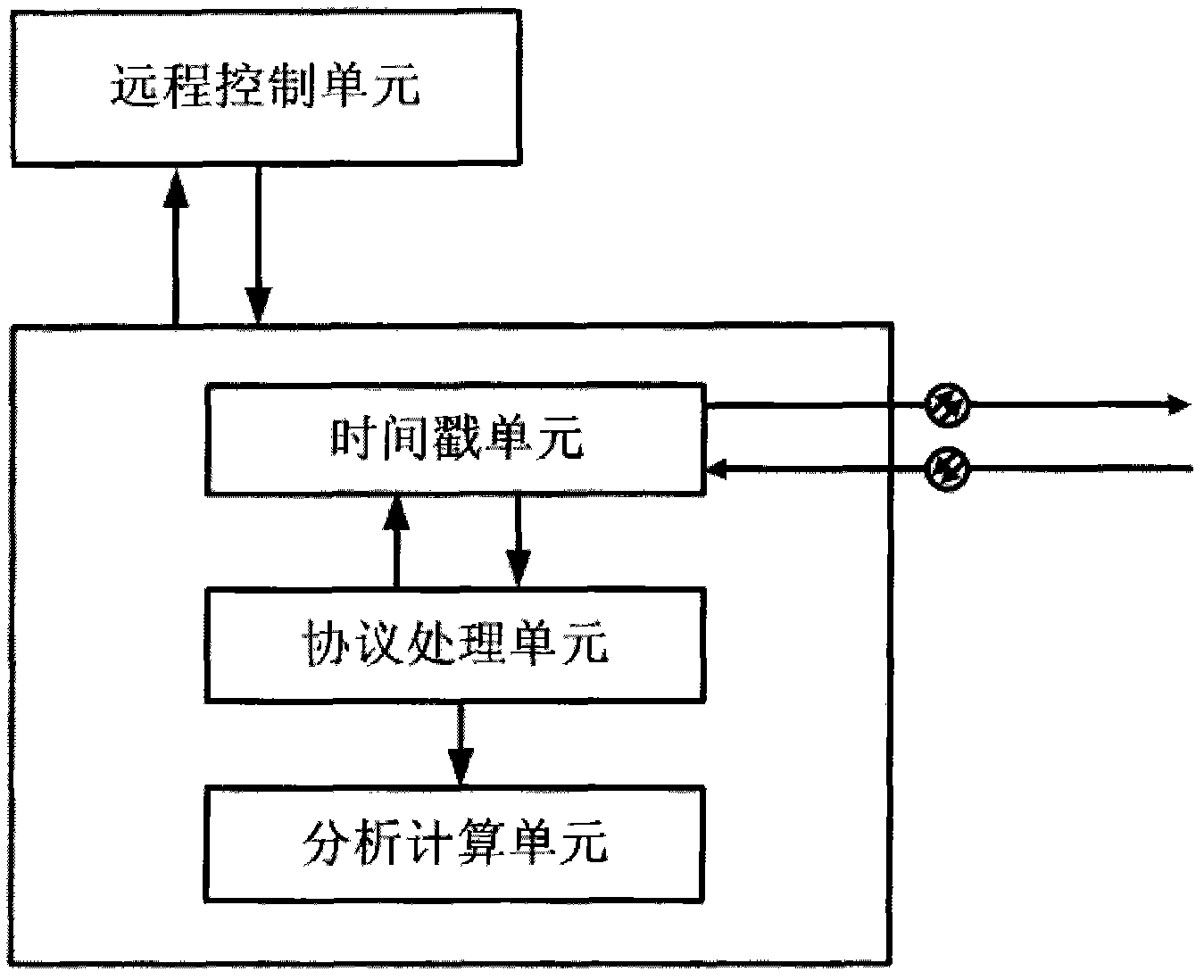
[0037] see figure 1 As shown, the device for measuring the time delay of optical fiber asymmetry provided by the embodiment of the present invention includes a TSU (Timestamp Unit, time stamp unit), a PPU (Protocol Processing Unit, protocol processing unit), and ACU (Analysis and Calculation Unit, analysis calculation unit) unit) and RTU (Remote control unit), where:
[0038] The TSU is used to generate and record the timestamp information t1 when the Master side sends a test packet, and according to the test packet mode, write the timestamp information t1 into the test packet or transmit the timestamp information t1 to the PPU; when the Slave side When the test message is received, the time stamp information t2 is generated and recorded. The TSU needs to ensure sufficient precision and stability, and the precision and stability of the time stamp will directly determine the precision and accuracy of the measurement.
[0039] The PPU is used to determine the test message mode: t1 is transmitted by test message or follow message. Send a test packet on the master side, obtain the timestamp information t1 at the time when the test packet is sent in the follow mode, and transmit t1 to the slave through the follower packet; receive the test packet on the slave side, and obtain the time stamp of the arrival time of the test packet. The timestamp information t2 is recorded corresponding to the t1 sent by the Master to prepare data for subsequent calculations;
[0040] After the ACU is used to collect time stamp information, it starts on the slave side, analyzes and calculates the collected data, obtains the asymmetric delay data of the optical fiber line, and calculates the asymmetric delay compensation value of the optical fiber line. ACU needs to analyze the collected data first, filter out data with large errors, and then perform calculations to ensure the accuracy of the resulting data.
[0041] RTU is used to set the working state of the test node, issue test instructions and feedback test results. Through the control of the remote control unit RTU, the measurement operation can be made simple, and by obtaining the feedback data, the test process can be monitored and the test results can be obtained in time.
[0042] The embodiment of the present invention is implemented in a PTN (Packet Transport Network, packet transport network) device, and the implementation and working modes of each part are described as follows:
[0043] The RTU is embedded in the network management equipment of the PTN system, and communicates with each node in the network through the network management system. The RTU configures the Master and Slave status of the test port through the network management interface, and configures the two nodes participating in the test. The system clock frequency is locked to the same time source to ensure that the Tslaveoffset (time offset value) between the two nodes remains stable. The RTU can issue test instructions through the page designed on the network management interface, and can observe the test status information and final measurement results fed back by the remote node.
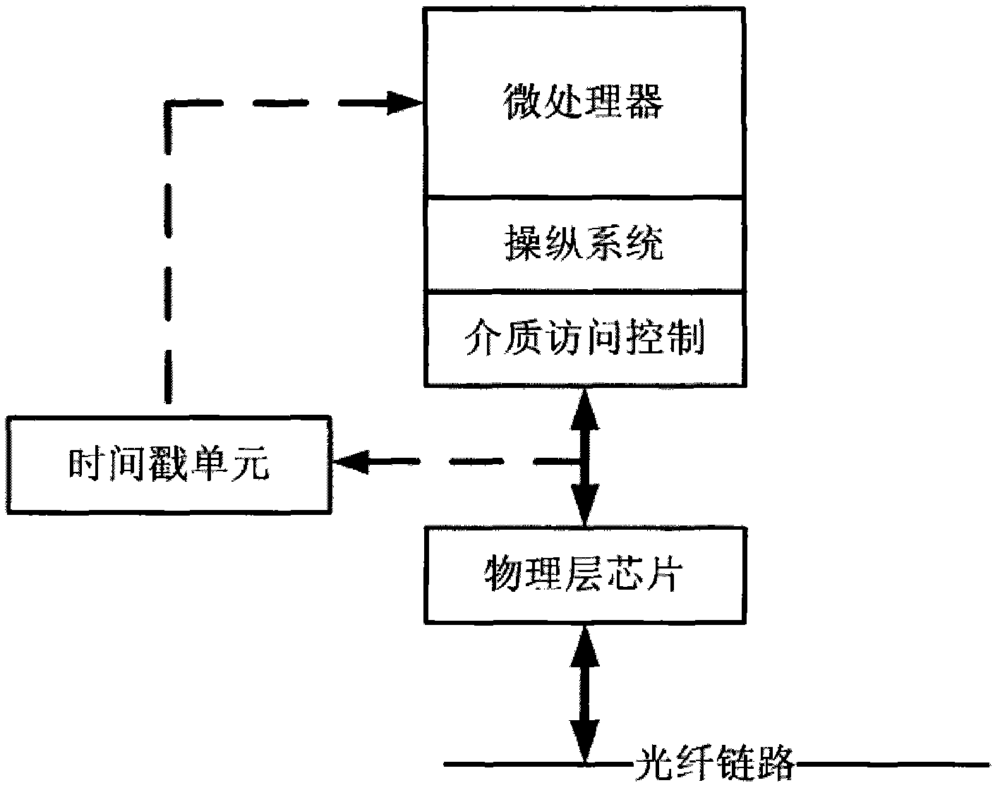
[0044] TSU can share the time stamp module of IEEE1588v2 time synchronization in the PTN system. For the working mode of TSU, see figure 2 shown. To ensure the accuracy of the time stamp, the TSU needs to identify the test packet and generate a time stamp at the moment when the test packet enters the line for transmission, and the moment when the test packet enters the TSU from the line and generates a time stamp. In the embodiment of the present invention, the TSU is located at the PHY (Physical Layer, physical layer chip) layer close to the line, and captures the message by identifying the target MAC (Medium/Media Access Control, medium access control) address of the test message, and the generated timestamp is finally Obtained by upper-layer application software. The TSU uses the system clock 125M to generate the time stamp, and the resulting system error is 8ns. Through the mean operation, the measurement error can be controlled within 16ns.
[0045] In the embodiment of the present invention, the PPU runs on the onboard CPU (Central Processing Unit, central processing unit), and uses the message format and time stamp transmission method in the PTP protocol to realize the test interaction between the master and the slave, and store the corresponding storage Required t1 and t2 data. Taking Sync (synchronization message) as a test message, triggers the TSU to generate t1 and t2, and transmits the t1 information to the Slave by following the message.
[0046] In the embodiment of the present invention, the ACU also runs on the onboard CPU, and after the measurement data collection is completed, the collected data is analyzed. After confirming the rationality of the data, the calculation is performed to calculate the final result that can be used to compensate the line asymmetry delay.
[0047] On the basis of the above device, the method for measuring optical fiber asymmetry time delay provided by the embodiment of the present invention includes the following steps:
[0048] (1) select the optical fiber line that needs to be tested, two optical fibers are included in the optical fiber line, and the remote control unit RTU configures the working state of the main port Master and the test slave port Slave of the optical nodes at both ends of the optical fiber line;
[0049] (2) The RTU issues an instruction to measure the first fiber, and the master-side protocol processing unit PPU continuously sends test packets, records the timestamp t1 of the time when each test packet is sent, and transmits t1 to the test packet or following the packet. Slave: Every time the PPU on the slave side receives a test packet, it records the time stamp t2 of the arrival time of the test packet, and stores it corresponding to the t1 sent by the Master; until t1 and t2 with sufficient groups are collected, it returns the first root to the RTU. Information about the completion of the fiber optic measurement;
[0050] (3) When the RTU displays the information that the measurement of the first optical fiber is completed and that the second optical fiber is ready to be measured, it informs the site to exchange the first optical fiber and the second optical fiber;
[0051] (4) The RTU issues an instruction to measure the second optical fiber, and the PPU on the Master side continuously sends test packets, records the timestamp t'1 of the time when each test packet is sent, and transmits t'1 to the Slave by following the packets; Each time the Slave side PPU receives a test packet, it records the time stamp t`2 of the arrival time of the test packet, and stores it corresponding to the t`1 sent by the Master; until a sufficient number of groups of t`1 and t`2 are collected, Notify the analysis computing unit ACU to start;
[0052] (5) ACU analyzes and calculates the collected data, and sends the compensation value t of the asymmetric delay of the optical fiber line to the RTU, t=(t1-t2+t`2-t`1)/2; if The ACU analyzes and finds that there is a problem with the collected data, and sends the information of test failure and re-test to the RTU.
[0053] The principle of the embodiment of the present invention is elaborated as follows:
[0054] The embodiment of the present invention utilizes the packet transmission and time stamp mechanism in the optical communication network, and collects two groups of time stamp data by measuring two optical fibers respectively in the same optical transmission direction. Then, by analyzing and calculating the collected time stamps, an accurate line asymmetry delay value can be obtained.
[0055] The basic analysis and calculation principles are as follows:
[0056] Assume that the 2 fibers between Master (test master port) and Slave (test slave port) are fiber 1 and fiber 2, respectively.
[0057] For fiber connection when measuring fiber 1, see image 3 As shown, after measuring the fiber 1, perform analysis and calculation: t2-t1=Tm2s+Tslaveoffset
[0058] Among them, t1 is the time stamp of the test message sending time recorded by the master, t2 is the time stamp of the test message receiving time recorded by the slave, Tm2s is the line delay caused by fiber 1 when the message is transmitted on fiber 1, and Tslaveoffset is the fiber connection The time offset value between the two test nodes.
[0059] For fiber connection when measuring fiber 2, see Figure 4 As shown, after replacing fiber 1 with fiber 2 for measurement, perform analysis and calculation: t`2-t`1=T`m2s+T`slaveoffset
[0060] Among them, t`1 is the time stamp of the test message sending time recorded by the master, t`2 is the time stamp of the test message reception time recorded by the slave, and T`m2s is the time stamp of the message when the message is transmitted by fiber 2 to the line brought by fiber 2 delay, T`slaveoffset is the time offset value between the 2 test nodes connected by the fiber.
[0061] When we ensure that the time deviation value between the two nodes is stable during the measurement process, that is
[0062] Tslaveoffset=T`slaveoffset
[0063] The asymmetric time delay value ΔT between fiber 1 and fiber 2 can be obtained by calculation,
[0064] ΔT=Tm2s-T`m2s
[0065] =(t2-t1-Tslaveoffset)-(t`2-t`1-T`slaveoffset)
[0066] =(t2-t1)-(t`2-t`1)
[0067] According to the PTP principle, the error caused by the line asymmetry delay to the time synchronization result is -ΔT/2. This value is directly calculated for the line asymmetry delay compensation, and the compensation value of the fiber line asymmetry delay The calculation process of t is as follows:
[0068] t=-ΔT/2
[0069] =【(t2-t1)-(t`2-t`1)】/2
[0070] =(t1-t2+t'2-t'1)/2.
[0071] A test example of line asymmetry delay is described in detail below.
[0072] For the topology diagram of the test network in the embodiment of the present invention, see Figure 5 As shown, using the time analyzer measurement data as the comparison data, a complete test operation process is as follows:
[0073] (1) Configure the clock frequency synchronization time analyzer. The GE port of node 1 of the test line is configured as the master, and the GE port of node 2 is configured as the slave. In this way, the M2S direction refers to the direction from node 1 to node 2, and the S2M direction refers to the direction from node 2 to node 1.
[0074] (2) Send a test instruction to node 2 through the network management, and start testing fiber 1.
[0075] (3) Check the test status of fiber 1. When the test status of fiber 1 shows success, swap the M2S fiber with the S2M fiber. See Figure 4 shown.
[0076] (4) The test command is given to the node 2 through the network management, and the test of the fiber 2 is started.
[0077] (5) Check the test status of fiber 2. When the test status of fiber 2 is displayed as successful, the test results are also displayed together.
[0078] (6) Record the test result and set it on the corresponding port of the network management to complete the compensation for the line asymmetry delay.
[0079] The test process and data records are as follows:
[0080] a, the same fiber test
[0081] Verify the accuracy and stability of the fiber change timestamp test method. Connect 2 optical fibers of equal length to the test line, and the length of the optical fibers is about 2 meters. The direction of fiber 1 is M2S, and the direction of fiber 2 is S2M, which compensates the error caused by the delay of the input and output lines to the time analyzer test. No fiber exchange operation was performed, and 10 measurement operations were performed on fiber 1, and the recorded data are shown in Table 1.
[0082] Table 1. Test results of the same fiber
[0083] Testing frequency
[0084] b. Asymmetric fiber test
[0085] Verify test stability and test accuracy for 2 asymmetry cases. Replace the fiber 1 in the original M2S direction with an optical fiber with a length of about 20 meters, and the fiber 2 in the S2M direction remains unchanged, and the length is still 2 meters. Start the test. After the test of item 1 is completed, the optical fibers are replaced, that is, the M2S direction is changed to fiber 2, and the S2M direction is changed to fiber 1. After the test of item 2 is completed, the test data and the measurement data of the time analyzer are recorded. If the fiber is not restored, start the next round of item 1 test directly, and then change the fiber to perform item 2 test. This cycle is repeated, so the results are alternately positive and negative. The test results are shown in Table 2.
[0086] Table 2. Test results of asymmetric fibers
[0087] Testing frequency
[0088] c, 24 km asymmetric fiber test
[0089] Verify test stability and test accuracy of long fiber condition. Swap fiber 1 in the M2S direction to a fiber with a length of 24,463 meters, and fiber 2 in the S2M direction remains unchanged, and the length is still 2 meters. The test steps are as above, and the data of 10 tests are recorded.
[0090] Table 3. Test results of 24km asymmetric fiber
[0091] Testing frequency
[0092] From the above test results, it can be concluded that the measurement accuracy and stability of the fiber change time stamp test method are very good.
[0093]It will be apparent to those skilled in the art that various modifications and variations can be made in the present invention without departing from the spirit and scope of the invention. Thus, provided that these modifications and variations of the present invention fall within the scope of the claims of the present invention and their equivalents, the present invention is also intended to include these modifications and variations.
[0094] Contents not described in detail in this specification belong to the prior art known to those skilled in the art.