A street light tube life monitoring system

A lamp life and monitoring system technology, applied in the direction of discharge tube testing, lighting devices, light sources, etc., can solve the problems of affecting road lighting, wasting electric energy, wasting manpower and material resources, etc., to achieve convenient road lighting, simple structure, and energy saving Effect

Inactive Publication Date: 2011-12-21
德清县伊科爱能电子科技有限公司
View PDF4 Cites 7 Cited by
  • Summary
  • Abstract
  • Description
  • Claims
  • Application Information

AI Technical Summary

Problems solved by technology

[0003] At present, more than 90% of the road lighting uses high-pressure gas discharge lamps. We cannot detect the service life of the lamp tubes. Only when the lamp tubes are completely unusable can we find o

Method used


Image

  • A street light tube life monitoring system
  • A street light tube life monitoring system
  • A street light tube life monitoring system

Examples


Embodiment 1

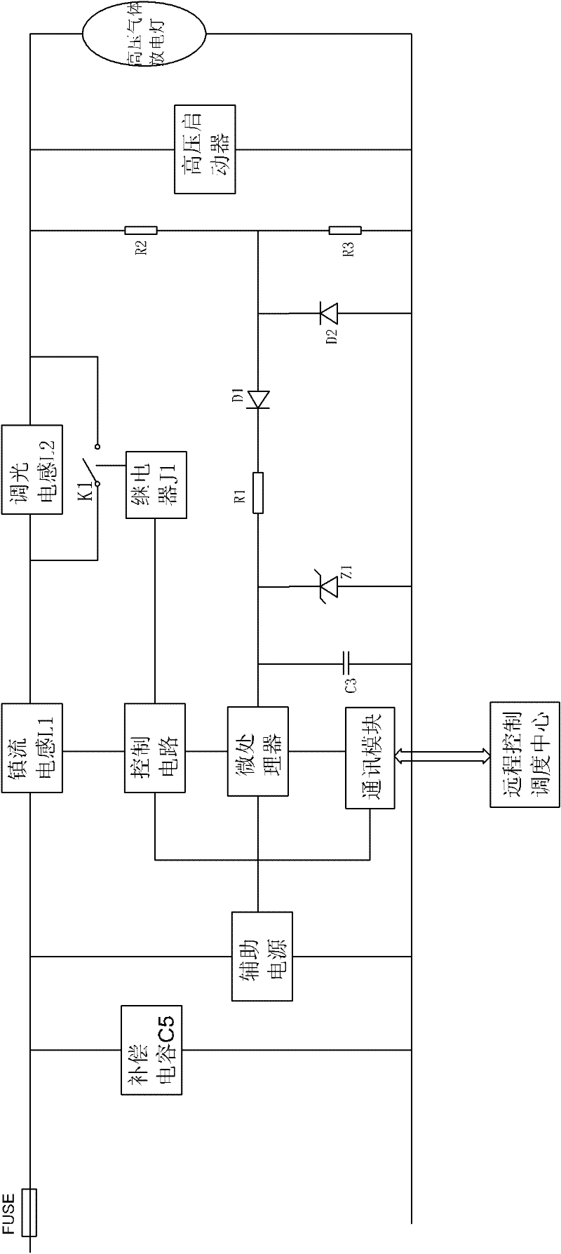
[0022] Such as figure 1 , a street lamp tube life monitoring system, including a ballast system and a remote control dispatch center, the ballast system includes a ballast inductor L1 connected to the lamp tube, a compensation capacitor C5 and a high-voltage starter; the remote control dispatch center through a communication network Connect the voltage detection circuit set at both ends of the lamp tube. The voltage detection circuit includes a voltage dividing capacitor C1, a voltage dividing capacitor C2, a detection diode D1, a filter capacitor C3, a resistor R1, a voltage regulator tube Z1, and a protection diode D2; the voltage dividing capacitor C1 and The voltage dividing capacitor C2 is connected in series to both ends of the lamp tube, the common end of the voltage dividing capacitor C1 and the voltage dividing capacitor C2 is connected to the positive pole of the detection diode D1, the negative pole of the detection diode D1 is connected to the resistor R1, the resis...

Embodiment 2

[0031] Such as figure 2 , a street lamp tube life monitoring system, including a ballast system and a remote control dispatch center, the ballast system includes a ballast inductor L1 connected to the lamp tube, a compensation capacitor C5 and a high-voltage starter; the remote control dispatch center through a communication network Connect the voltage detection circuit set at both ends of the lamp tube, the voltage detection circuit includes voltage divider resistor R2, voltage divider resistor R3, detection diode D1, filter capacitor C3, resistor R1, voltage regulator tube Z1, protection diode D2; voltage divider resistor R2 and The voltage divider resistor R3 is connected in series to both ends of the lamp tube, the common end of the voltage divider resistor R2 and the voltage divider resistor R3 is connected to the positive pole of the detection diode D1, the negative pole of the detection diode D1 is connected to the resistor R1, the resistor R1 is connected to the filter...


PUM


Abstract

The invention discloses a system for monitoring the life of a street lamp tube, which includes a ballast system and a remote control dispatch center. The ballast system includes a ballast inductor L1 connected to the lamp tube, a compensation capacitor C5 and a high-voltage starter; the remote control dispatch center passes The communication network is connected to the voltage detection circuit set at both ends of the lamp tube. When the high-pressure gas discharge lamp is working, there will be a fixed tube voltage at both ends of the lamp tube. After the voltage is divided by the voltage dividing capacitor C1 and the voltage dividing capacitor C2, the voltage regulator Z1 will divide the voltage. Clamp at a fixed value to protect the voltage detection circuit from being damaged. The detection circuit composed of detection diode D1, resistor R1 and filter capacitor C3 converts the divided high frequency and low voltage into DC voltage V1, and the remote control dispatching center will The DC voltage value is compared with the preset voltage value to judge the life of the lamp tube. When the service life of the lamp tube is about to expire, the remote control dispatching center will timely report the detected lamp life information so that relevant personnel can deal with it in time.

Description

[0001] technical field [0002] The invention relates to a street lamp monitoring system, in particular to a street lamp monitoring system capable of testing the service life of lamp tubes. Background technique [0003] At present, more than 90% of the road lighting uses high-pressure gas discharge lamps. We cannot detect the service life of the lamp tubes. Only when the lamp tubes are completely unusable can we find out and deal with them through manual inspections, which will waste a lot of manpower and material resources and affect normal road lighting. , increase the hidden danger of accidents, and waste electric energy. Contents of the invention [0004] The purpose of the present invention is to overcome the deficiencies in the prior art and provide a street lamp monitoring system capable of detecting the service life of lamp tubes, prompting replacement of lamp tubes in time, and reducing hidden dangers of accidents. [0005] The technical solution of the present i...

Claims


Application Information

Patent Timeline
IPC IPC(8): H05B41/38G01R31/24
CPCY02B20/72
Inventor 罗晓东
Owner 德清县伊科爱能电子科技有限公司
Why Eureka
Try Eureka