Phased array antenna alignment method and device and phased array antenna

A phased array antenna and alignment device technology, applied in the field of communication, can solve problems such as low automation, low precision, and slow speed, and achieve the effect of high automation and improved work efficiency

Active Publication Date: 2011-12-21
HUAWEI TECH CO LTD
View PDF5 Cites 53 Cited by
  • Summary
  • Abstract
  • Description
  • Claims
  • Application Information

AI Technical Summary

Problems solved by technology

Using the traditional mechanical method to rotate the antenna, the inertia of the antenna is large, the accuracy is low, and the degree of automation is low and the speed is slow, which obviously cannot meet the needs of modern communication.

Method used


Image

  • Phased array antenna alignment method and device and phased array antenna
  • Phased array antenna alignment method and device and phased array antenna
  • Phased array antenna alignment method and device and phased array antenna

Examples


Embodiment 1

[0036] Phased array antenna (Phased array antenna) is an antenna that uses electronic control to change the phase of the radiating elements in the array, so that the beam scans the space as required. It changes the shape of the pattern by controlling the feeding phase of the radiating elements in the array antenna. Controlling the phase can change the direction of the maximum value of the antenna pattern to achieve the purpose of beam scanning. The pattern shows the directional characteristics of the energy transmitted (or received) by the antenna. The characteristics of the energy transmitted by the antenna are expressed by the transmission pattern, and the characteristics of the energy received by the antenna are expressed by the reception pattern. Generally speaking, the shapes of the transmit pattern and the receive pattern of an antenna coincide. The scanning speed of the phased array antenna beam is high, the feeding phase is controlled by an electronic computer, and th...

Embodiment 2

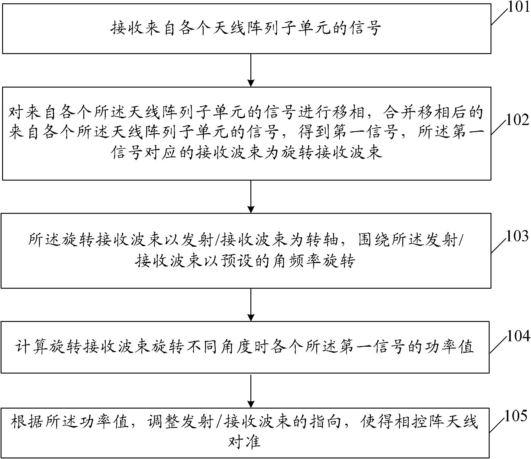
[0054] This embodiment provides a phased array antenna alignment method, such as Figure 4 and Figure 5 As shown, the method includes:

[0055] Step 201, initialize the direction of the transmit / receive beam to be the normal direction of the plane where the phased array antenna is located. The direction of the transmit / receive beam 51 here is the direction of the phased array antenna.

[0056] Step 202, initialize the direction of the rotating receiving beam 11 as (θ, φ), where,

[0057] θ represents the angle between the rotating receiving beam 11 and the transmitting / receiving beam 51, that is, the deflection angle relative to the transmitting / receiving beam 51. In this embodiment, θ is greater than 0°, and the preferred value range is 0<θ<90° ;

[0058] Since when the angle θ between the receiving beam and the local transmitting / receiving beam is a certain value, if the width of the main lobe of the antenna is relatively wide, the fluctuation range of the collected dat...

Embodiment 3

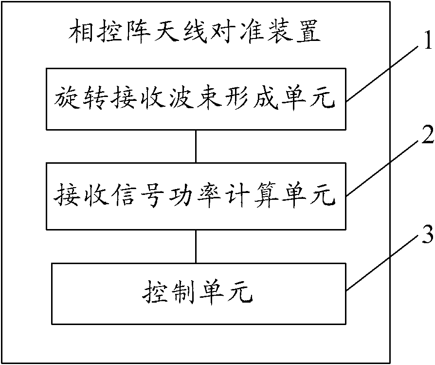
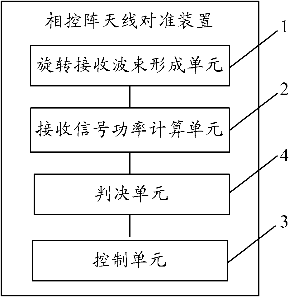
[0075] This embodiment provides a phased array antenna alignment device, such as figure 2 and image 3 As shown, the device includes: a rotating receiving beamforming unit 1, a receiving signal power calculating unit 2 and a control unit 3, wherein:

[0076] The rotating receive beamforming unit 1 is used to receive signals from each antenna array subunit; phase-shift the signals from each antenna array subunit, and combine the phase-shifted signals from each antenna array subunit to obtain a first signal, the receiving beam corresponding to the first signal is a rotating receiving beam;

[0077] The rotating receiving beam takes the transmitting / receiving beam as a rotation axis and rotates around the transmitting / receiving beam at a preset angular frequency.

[0078] like Figure 8As shown, the rotating receiving beamforming unit of this embodiment includes: a plurality of phase shifters 12, a power divider 13 and a beam pointing control module 14, wherein the power divi...


PUM


Abstract

A method and an apparatus for aligning a phased array antenna, and a phased array antenna are provided. A method for aligning a phased array antenna according to an embodiment of the present invention includes: receiving signals from respective antenna array subunits; performing phase shifting on the signals from the respective antenna array subunits, combining phase-shifted signals, where the signals are from the respective antenna array subunits, and obtaining a first signal, where a receiving beam corresponding to the first signal is a rotating receiving beam; rotating, by the rotating receiving beam, around a transmitting / receiving beam according to a preset angular frequency by using the transmitting / receiving beam as a rotation axis; calculating power values of respective first signals in a case that the rotating receiving beam rotates through different angles; and adjusting, according to the power values, a direction of the transmitting / receiving beam to align a phased array antenna.

Description

technical field [0001] The present invention relates to the communication field, in particular to a method and device for aligning a phased array antenna and a phased array antenna. Background technique [0002] At present, the antenna alignment method in the prior art is usually to manually rotate the antenna using traditional mechanical methods, and then adjust the horizontal or pitch direction of the antenna, and at the same time detect the signal strength received by the antenna: when the detected signal strength reaches a certain The antenna is considered to be aligned when it is within range. [0003] Due to factors such as the aging of the antenna's fasteners, thermal expansion and cold contraction, etc., the antenna pointing will change to a certain extent, resulting in a decline in communication quality; If the situation causes the antenna to shake, it may cause instantaneous or unrecoverable service interruption. Therefore, it is necessary to manually maintain th...

Claims


Application Information

Patent Timeline
Patent Type & Authority Applications(China)
IPC IPC(8): H01Q3/00H01Q3/30H01Q21/00
CPCH01Q3/30H01Q3/00H01Q3/267H01Q21/00G01S3/56
Inventor 陈一
Owner HUAWEI TECH CO LTD
Why Eureka
Try Eureka