Processing Technology of Small Diameter, Thin Wall, Deep Hole and High Precision Parts and Its Special Grinding Tools

A processing technology and small diameter technology, applied in the field of mechanical processing technology, can solve problems such as design requirements and processing difficulties of difficult cylinder parts

Inactive Publication Date: 2011-12-28
HARBIN JIANCHENG GRP
View PDF4 Cites 20 Cited by
  • Summary
  • Abstract
  • Description
  • Claims
  • Application Information

AI Technical Summary

Problems solved by technology

[0003] The purpose of this invention is to solve the problem that it is difficult to meet the design requirements and processing difficulties of cylinder parts by using conventional machining methods, and to provide a processing technology for small-diameter, thin-walled, deep-hole, high-precision parts and its special grinding tool

Method used


Image

  • Processing Technology of Small Diameter, Thin Wall, Deep Hole and High Precision Parts and Its Special Grinding Tools
  • Processing Technology of Small Diameter, Thin Wall, Deep Hole and High Precision Parts and Its Special Grinding Tools
  • Processing Technology of Small Diameter, Thin Wall, Deep Hole and High Precision Parts and Its Special Grinding Tools

Examples


specific Embodiment approach 1

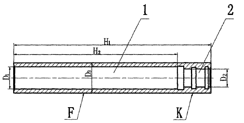
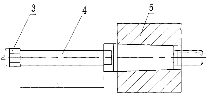
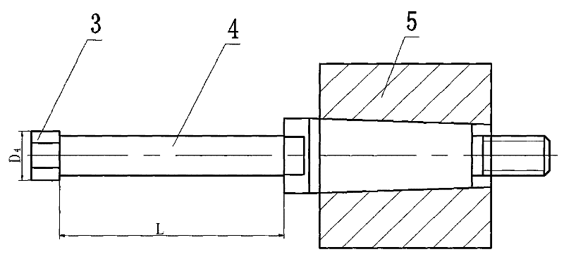
[0011] Specific implementation mode one: combine figure 1 and figure 2 Describe this embodiment, the step of the processing technology of the small-diameter thin-walled deep-hole high-precision part of this embodiment is:

[0012] Step 1. The blank is made of round steel, and the outer circle of the blank is processed by the turning process, and the end faces on both sides of the part are flattened to ensure that the total length of the part is H 1 , and drill a center hole at the center of the end faces on both sides; on the lathe, adopt the clamping method of tightening the center holes of the end faces on both sides, and turn the outer circle to the design diameter D 3 , during the turning process, use a dial gauge to make a calibration, to ensure that the straightness of the outer circle is less than or equal to 0.005mm, and the coaxiality is less than or equal to 0.005mm;

[0013] Step 2. Turning the inner hole. Clamp the part with a three-jaw chuck on the lathe, suppo...

specific Embodiment approach 2

[0016] Embodiment 2: This embodiment differs from Embodiment 1 in that: the jaws of the three-jaw chuck in step 2 are wrapped with thin aluminum sheets. Prevent the jaws from directly acting on the outer circle of the part and destroying the surface finish of the part.

specific Embodiment approach 3

[0017] Embodiment 3: This embodiment is different from Embodiment 1 or 2 in that: during rough turning in step 2, the inner hole turning tool with a relief angle of 4° to 6° is selected, and during finish turning, the relief angle is selected to be 8° ~12° inner hole turning tool. In order to reduce the friction between the flank and the part, avoid the increase of cutting heat and improve the surface roughness; when finishing the inner hole, the rake angle should be increased to make the cutting edge sharp, reduce deformation and friction, and generate less heat for cutting The temperature drop can save cutting effort and make the chip discharge smoothly.


PUM


Abstract

The invention relates to a processing technology of small-diameter, thin-walled, deep-hole, high-precision parts and its special grinding tool, which relates to a processing technology of thin-walled, deep-hole, high-precision parts and its special grinding tool. The invention solves the problems that it is difficult to meet the design requirements and processing difficulties of the cylinder body parts by conventional mechanical processing methods. The process steps of the present invention are as follows: turning the outer circle and end face of the blank, and adopting a stepwise progressive drilling method to drill through the first inner hole and the second inner hole layer by layer; The head rotates, and the parts make a low-speed rotary motion relative to the grinding head, and the grinding head grinds the parts to complete the processing of the parts. The end of the extended handle of the grinding tool adopts a Morse taper structure, and the grinding head is fixedly installed at the head end of the extended handle. The grinding head is made of white jade, and the extended handle is made of alloy tool steel. The processing technology of the invention is especially suitable for the manufacturing technology of small-diameter, thin-walled, deep-hole and high-precision parts in the field of mechanical processing.

Description

technical field [0001] The invention relates to a processing technology of thin-walled deep-hole high-precision parts and a special grinding tool thereof, belonging to the technical field of mechanical processing technology. Background technique [0002] There are many cylinder parts, especially the cylinder of the wing tension mechanism is one of the representative parts of the cylinder. The cylinder body is a small-diameter, thin-walled, deep-hole part, and the machining precision of the inner hole is high (see attached figure 1 ), the cylinder body will encounter many problems during processing, and it is difficult to realize it by conventional mechanical processing methods, and it is difficult to meet the design requirements. The most prominent feature is that the tool bar is thin and long during turning, the hole wall is thin, the tool bar rigidity is poor, the strength is low, and it is easy to generate large vibration and tool drop phenomenon, and the taper error wil...

Claims


Application Information

Patent Timeline
Patent Type & Authority Applications(China)
IPC IPC(8): B23P13/00B24B5/48
Inventor 武晓燕闫明春赵源东高立栋张明
Owner HARBIN JIANCHENG GRP
Why Eureka
Try Eureka