Eureka AIR delivers breakthrough ideas for toughest innovation challenges, trusted by R&D personnel around the world.

A hook and a railway vehicle including the hook

A railway vehicle and knuckle technology, which is applied in the field of railway vehicle knuckles, can solve problems such as cracks and breakage of the knuckle, and achieve the effects of reducing cracks, facilitating transportation, and improving work reliability

Active Publication Date: 2011-12-28
CRRC QIQIHAR ROLLING CO LTD
View PDF9 Cites 8 Cited by
  • Summary
  • Abstract
  • Description
  • Claims
  • Application Information

AI Technical Summary

Problems solved by technology

At present, in the existing technology, the knuckles for railway vehicles are all manufactured by casting process, but because the casting process will inevitably lead to fatigue crack sources such as trachoma, shrinkage cavity, shrinkage porosity, etc., it is very easy to cause cracks in the knuckle during use or break

Method used


Image

  • A hook and a railway vehicle including the hook
  • A hook and a railway vehicle including the hook
  • A hook and a railway vehicle including the hook

Examples


Embodiment Construction

[0028] The core of the present invention is to provide a knuckle, which can effectively improve its working reliability, has low material cost and is easy to carry. In addition, another core of the present invention is to provide a railway vehicle including the knuckle.

[0029] In order to enable those skilled in the art to better understand the technical solutions of the present invention, the present invention will be further described in detail below in conjunction with the accompanying drawings and specific embodiments.

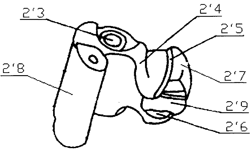
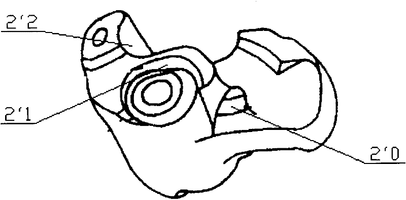
[0030] Please refer to Figure 4 , Figure 5 , Figure 6 and Figure 7 , Figure 4 It is a structural schematic diagram of a knuckle in an embodiment of the present invention; Figure 5 for Figure 4 Middle E-E sectional view; Figure 6 for Figure 4 Right view of middle knuckle; Figure 7 for Figure 4 Left view of the middle knuckle.

[0031] In one embodiment, as Figure 6 and Figure 7 As shown, the knuckle provided by the present invent...


PUM

PropertyMeasurementUnit
thicknessaaaaaaaaaa
depthaaaaaaaaaa
depthaaaaaaaaaa

Abstract

A coupler knuckle for railway vehicle has a draft surface (1) and a knuckle pivot pin hole (2). A bounce table (3) lies on the knuckle pivot pin hole (2), and a traction table (4) lies on the bounce table (3). A nose (5) of the coupler knuckle is provided in the lower part of the coupler knuckle. The bottom surface of the coupler knuckle's nose forms the coupler knuckle's face (6). There is a first groove (61) on the coupler knuckle's face (6). The coupler knuckle is a forging piece. The coupler knuckle has the advantage of high reliability, low cost and is easy to be transported.

Description

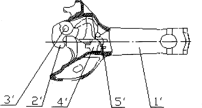
technical field [0001] The invention relates to the technical field of railway vehicles, in particular to a knuckle used for railway vehicles. In addition, the present invention also relates to a railway vehicle including the aforementioned knuckle. Background technique [0002] Generally speaking, a railway vehicle is mainly composed of a car body, a running part, a braking device, a coupler buffer device and internal equipment of the vehicle. The coupler is an important part of the coupler buffer device. The coupler is used to realize the connection between the railway locomotive and the vehicle or between the vehicle and the vehicle, transmit traction and impact force, and keep a certain distance between the vehicles. [0003] Please refer to figure 1 , figure 1 It is a structural schematic diagram of an automatic coupler for a railway vehicle in the prior art. [0004] The coupler that railway vehicle uses in the world is mainly automatic coupler at present, and so-c...

Claims


Application Information

Patent Timeline
Patent Type & Authority Applications(China)
IPC IPC(8): B61G3/10
CPCB61G3/10B23P15/20
Inventor 姜岩孟庆民景丹崔英俊孙红吉王长春于跃斌王俊龙卜文学
Owner CRRC QIQIHAR ROLLING CO LTD
Why Eureka
Eureka Blog
Learn More